
Integrating 3D structural analysis and piping design drastically reduces man- hours on design of chemical plant
By Fred Adam and Todd Hancock
Eichleay Engineers of California
Table of Contents
Summary
Introduction
Chemical refinery
Better strategy
3D for piping
Many other benefits
Summary
Eichleay Engineers of California (Concord, CA) linked structural analysis with plant design software to shrink design time for a chemical plant's structural steel framework by a factor of over 50%. After drawing the centerlines of steel members in the plant design program, engineers transferred the geometry to a structural analysis program. There, the members were sized to meet required loads. This information was transferred back to the plant design system's structural steel module, which then generated a 3D model of the framework automatically from the analysis data. The alternative, modeling and sizing a 3D component representing each individual member, would have taken approximately 2 to 3 times as long. Eichleay Engineers used the plant design system's 3D piping module with automatic isometric capabilities to compress the design cycle even further. Having a 3D plant model not only saved time, however. It saved fabrication costs and also helped purchasing, plant operations, and maintenance personnel understand the design and give valuable input early in the project. The 3D model will be used throughout the lifecycle of the plant.
Introduction
Eichleay Engineers of California is an affiliate of Eichleay Holdings, which is headquartered in Pittsburgh, Pennsylvania. The California group, approximately 150 people, specializes in the design and construction of process plants and manufacturing facilities. Eichleay Engineers of California has adopted a model-centric design process in which a 3D CAD model is created for use by all design disciplines. By using a 3D model of the project as the central focus of the design process; the initial design concept, the interim product, and the finished design all share a common database and represent the collaborative input from the design team. Eichleay finds that this project approach improves communication, minimizes errors, and facilitates the understanding of real issues. The company utilizes cutting edge technology to provide their clients with projects that meet or exceed their highest standards and position their project on fast tracks toward fabrication, construction, and operation.
Chemical refinery
Eichleay was hired to design the facilities required to install a new process unit at their clients refinery. The owner of the facility had purchased the proprietary process equipment for from a major equipment manufacturer and hired Eichleay Engineers of California to design a plant to house it. Eichleay began the design process by creating digital models of the process equipment using specifications and drawings supplied by the manufacturer. The modeling was done using the equipment module of the plant design system, AutoPLANT 97 from Rebis (Walnut Creek, CA). This family of 3D plant design software runs as an add-on to Autocad. The company chose AutoPLANT 97 because it is the only low cost program that addresses all aspects of plant design including equipment, structural steel, piping, isometrics, and interference detection.
The next step was to create a model of the structural steel framework, which had a relatively small footprint of about 50 feet by 75 feet and five stories tall at its highest point. After establishing the approximate locations of the various equipment models, a general scheme of the structural system was developed.
For many companies, the next step would be to size the steel members in the CAD system. One problem with this approach is that it is time-consuming to create a properly sized 3D CAD model of each steel member, In a plant such as the one Eichleay was designing, between the structural steel framework and all the cross bracing and support framing, there are hundreds of members.
Another problem is that sizing the steel is mostly guesswork at this point. Not until the next step, structural analysis, is it evident whether the sizing has been done correctly. Using a computer analysis program or hand calculations, engineers evaluate whether the members can withstand the required loads, such as the weight of filled storage vessels. If the analysis indicates overstressed members, the engineer then goes back to the CAD model, to resize the appropriate members, and repeats the analysis. This process can involve many iterations and can be very time-consuming.
Better strategy
Eichleay Engineers of California has developed a more efficient approach to sizing steel members and analyzing them for structural stability. For this particular plant, which offers a good example of their approach, the design study model did not include any detailed modeling of the members. Only the center lines (simple endpoint to endpoint lines) of the steel members were created, in a model known as a space frame. The space frame geometry was exported to the STAAD structural analysis program from Research Engineers, Inc., Yorba Linda, California. STAAD is a general-purpose, integrated design and analysis program suitable for practically all kinds of structures. In STAAD, an engineer sized and loaded the members, running the analysis and repeatedly refining the model to the point where it would perform adequately given the loads it would have to handle.
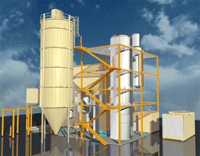
Eichleay's design study model
Sizing the steel members in the program offers the convenience of being able to change them easily in response to the analysis results. Without leaving the analysis program, the engineer simply makes changes to the structural model and repeats the analysis, But sizing the members properly within the analysis program would be an additional, time-consuming step if they had to be sized again within the CAD system to create the 3D plant model. An important component of Eichleay's strategy is the ability to use the STAAD data within the plant design system to size the members automatically.
The company developed a proprietary program that takes the STAAD output files, combines them into one .SXF (simulation exchange file) file, and reads the information into a component of AutoPLANT 97 called Multi-Steel. Multi-Steel Modeler provides modeling and drafting functions to model 3D structural steel including drawing setup and creation, 3D grid placement, steel placement and database management, steel editing and display options, steel annotation. and access way (stairs, ladders, platforms, and handrails) placement. Like other AutoPLANT modules, Multi-Steel has an object-oriented foundation. This allows it to convert basic information such as lines and mass properties into intelligent steel members.
The program that Eichleay used links Multi-Steel with the necessary information from STAAD to automatically generate a 3D model of the structural steel framework containing properly sized steel members. The time savings that result from not having to size each member individually are enormous. On this project, engineers estimate that structural steel design would have taken two to three times as long without this capability. The approach is so efficient that Eichleay also uses it when changes to the structural steel design are needed. Changes are made in STAAD, then exported to Multi-Steel, which replaces the old structure with an entirely new one, They find that this is faster than making changes within the plant model, then going back and forth between the plant design program and analysis to ensure that the new design meets the structural requirements.
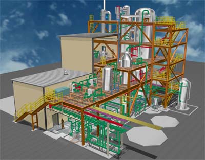
Sample iteration (close to finished design)
3D for piping
In keeping with Eichleay Engineers of California's 3D model-centric design approach, the piping for this plant was also modeled in 3D. For the piping designer, this was somewhat different from the conventional 2D approach that would have begun with roughing out a layout that established rough equipment placements.
The next step would have been to prepare the piping plan and elevation views required to connect the equipment. Elevation views would have been created from scratch. Every plan and section view as well as all bills of material would also have been created manually from scratch.
In this project, the equipment was placed within the 3D AutoPLANT model earlier, when the design study model was created. The piping designer started at a pump and proceeded placing pipe until he reached an appropriate vessel. He had more than 100 lines to model. As he worked, he included elevation, routing a pipe 20 feet horizontally, for example, then up 10 feet, and then horizontally another 20 feet. Once he had all the pipes in place, he came back and added the fittings and valves. Rebis' AutoPIPE software for pipe stress analysis was then used to make sure that the pipes were properly supported AutoPIPE is a native Windows program for calculation of piping code stresses, loads, and deflections under static and dynamic loading conditions. This piping program is thoroughly integrated with 3D plant design CAD systems, fluid flow analysis, structural steel, and piping pulsation and acoustic analysis. Engineers can download an entire system from CAD into AutoPIPE for analysis, calculate stresses and loads, and iterate between piping flow and piping acoustic analysis for "what if" design scenarios.
The primary benefit to working in 3D showed up in the production of piping isometrics. Using the Auto-Iso feature of AutoPLANT, the designer was able to spin off isometrics automatically from the 3D model. Some touch-up was required to make the drawings conform to the company's standards, but overall the ability to generate isometrics from the 3D model reduced the time needed to prepare them by about 50%. Other required documents, such as plan views, section views, and bills of material were also generated automatically, for additional time savings.
Many other benefits
Having a 3D model of this plant provided numerous other benefits in addition to saving time during the design cycle. All design reviews were conducted using the 3d model, including the first one that took place 30 days into the project, Other design development reviews were held at 30%, 60% and 90% of design completion. Clients were able to view walk-through of the 3D model at each of these reviews, and because they could understand exactly what they were seeing, their input was more valuable than if they had tried to visualize the design from 2D drawings.
A 3D model offers greater accuracy than a series of drawings, and in this project that is paying off in several ways. Now that construction is underway, the components are fitting together perfectly. This is because interferences were detected and fixed in the model. In addition, Eichleay's initial estimate of the amount of steel required, prepared at the 30-day point, turned out to be accurate to within four tons. The ability to accurately predict steel requirements so early helped reduce Costs by allowing early estimates of the amount of steel required. This information could not have been determined until much later in the project. Also, because the information from the 3D model has been so precise, construction has proceeded on budget and on schedule.
Information from the 3D model created by Eichleay will be used throughout the lifecycle of this plant. Obviously, the data is required for construction, but it has value for many aspects of the plant's ongoing operation, including purchasing, training, and maintenance. Representatives from these groups were present at the design reviews and their input was used to work out problems early in the design process. They will continue to use information from the model during start-up and also once the plant is in operation. Eventually, the model may be used for decommissioning the plant as well.
As this project illustrates Eichleay's model-centric design approach offers significant time and cost savings during design, construction, and throughout the lifecycle of a plant. On this particular plant, at least 50% of the design man-hours normally budgeted were saved in structural steel design alone. Many more were saved by the automatic spin off of isometrics and other documentation from the 3D model. Cost savings are now in evidence as the plant is being built. Creating an intelligent 3D model of a plant is an investment that pays off handsomely.
For more information: Fred Adam or Todd Hancock, Eichleay Engineers of California, 1390 Willow Pass Rd., Suite 600 Concord, CA 94520. Tel: 510-689-7000. Or: Rebis, 1600 Riviera Ave. Suite 300, Walnut Creek, CA 94596. Tel: 925-933-2525. Fax: 925-933-1920.
Edited by Angelo DePalma
Managing Editor, Pharmaceutical Online