
A New Approach in Plant Physical Documentation and Information Management for Existing Facilities

Dr. Moh Hashemi, P.E. & David S. Reinhart
INOVx Solutions
Contents
Traditional Plant Documentation – The Manual Approach
3D CAD: Applications in New and Existing Facilities to Date
A New Approach to Plant Documentation Using Integrated Technologies
What Makes a Successful Project?
Work Process
I. Project Planning
II. Site Planning
III. Field Documentation
IV. Analysis/Registration: Development of a Physical Database
V. Scoping the CAD Modeling
VI. CAD Modeling
VII. Engineering, Simulation and Information Management
Conclusions
Traditional Plant Documentation – The Manual Approach(Back to Top)
Plant physical documentation defines the "as-is" or "as built" conditions of the plan. It is often required for revamp/retrofit projects, as well as ongoing operation and maintenance activities. It consists of (1) the accurate dimensions and relative locations of all objects in a facility; and (2) classification of these objects by their appropriate engineering discipline (equipment, structural, electrical, civil, etc.).
Accurate, up-to-date documentation of the "as built" plant does not exist for many older facilities. Instead, these facilities typically use obsolete plot plans, elevation drawings, systems isometrics, or other two-dimensional manual or CAD drawings prepared during the original engineering and construction phase or during a major revamp or retrofit project.
The manual approach for collecting and updating plant physical conditions is commonly used for revamp/retrofit projects as well as plant maintenance and operation. While it generally lacks accuracy, engineers generally compensate with design contingencies and simply accept the rework cost associated with deviation from design. They understand that different engineering and operational disciplines must make multiple passes to collect manually the specific data they need, and accept the impact on both project budget and timeline. In addition, engineers rarely pass manually collected data among disciplines or between projects. This results in an ineffective use of collected data.
3D CAD: Applications in New and Existing Facilities to Date(Back to Top)
Newly completed plants often use 3D CAD models developed during the engineering and construction phases for physical documentation. Many owner/operators recognize the importance of these documents in operations, maintenance, and future revamps/retrofits. 3D models become living documents that are updated continuously as plant conditions evolve. 3D CAD models help engineers manage facilities, simplifying query and display of plant information. 3D models are effective plant data mining tools.
3D modeling has demonstrated positive engineering, construction, operational, and maintenance advantages in many new facilities. Achieving those results in existing facilities is something else again. Without accurate "as-is" engineering documentation, industry regards the development of complete, detailed, intelligent 3D models of existing facilities as expensive and impractical. Therefore, the owner/operators and engineering and construction companies rarely use 3D modeling technology for the revamp/retrofit projects and subsequent operation and maintenance.
A New Approach to Plant Documentation Using Integrated Technologies(Back to Top)
Laser scanning/imaging and close-range photogrammetry are effective technologies for physical documentation of existing plants. They are advanced three-dimensional measurement and visualization tools that can be used to develop 3D images and models of an existing facility. The resulting physical database can be used independently, or transformed into a complete and dimensionally accurate CAD model on a scalable and fit-for-purpose basis.
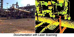 Laser scanning and imaging. The laser scanning and imaging process involves the use of a laser scanner to capture a "cloud of points." Each point in the cloud corresponds to the location of a point measured by the laser scan beam. A "cloud of points" describes the three-dimensional objects within the field of view of the scanner. A collection of "clouds of points" makes up a spatially accurate 3D database in which objects scanned can be reviewed, located, and measured by referencing them back to a series of surveying targets strategically located throughout the area prior to laser scanning.
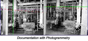 Photogrammetry. Photogrammetry is similar in many respects to laser scanning and imaging. In photogrammetry, the object itself is not measured. Rather, measurements are taken from stereo photos of the object. Multiple photos are taken of each area and referenced to the facility coordinate system by temporary adhesive targets, which are strategically located throughout the area, surveyed. The photos are linked to the survey points and used to determine additional three-dimensional coordinates through triangulated measurement, making it possible to accurately collect the location, sizes, and shapes of all visible objects within an operating plant.
Photogrammetry has been applied on numerous revamp and retrofit projects globally for more than a decade. In its developmental years, close range photogrammetry was used in Europe for documenting nuclear facilities during revamp/retrofit and dismantling projects. When compared to a manual approach, it significantly reduced the fieldwork needed to collect data and prepare CAD models. The benefits of photogrammetry for existing facilities are well documented in open literature.
Availability. Laser scanning and imaging is a newer data collection technology. It has the ability to create an instantaneous 3D representation of a scene, a "cloud of points." Laser scanning has proven on many projects to significantly reduce the cost and time required to collect data when compared to manual means.
Various types of photogrammetry technologies are available commercially. Photogrammetry is a mature technology, one that depends more on software than hardware or firmware in comparison with laser scanning. Most commercial photogrammetry packages offer reliable and accurate systems with similar functions. The differentiating characteristics between them are the cost and effectiveness of the 3D modeling activities.
At least four types of laser scanning systems are now available. Laser scanning, a less mature technology than photogrammetry, is highly dependent on hardware and firmware. Laser scanning systems differ in terms of cost, data collection targeting and range, portability, hardware and electronics reliability, availability, and maintainability. Currently, system reliability, availability, and maintainability are the key concerns of most users.
Combined application. Either of these technologies will easily capture many (but not all) areas of existing facilities in order to create a physical database. The combined use of both methods, however, provides today ‘s the most effective course for efficiently documenting up to 100% of an existing facility.
Laser scanning is the most effective tool for physically documenting hard-to-reach places. Photogrammetry provides the most effective method for imaging high-density areas with difficult access. Each technology has individual strengths. When used together, they complement one another to help create a complete physical database.
The effort required to develop a CAD model from the physical database is similar for the two technologies. The associated software for each system provides sophisticated processing and 3D model construction with user-friendly interfaces. In photogrammetry the models are constructed on top of photos by triangulation methods. In laser scanning and imaging the models are constructed by fitting geometric primitives to the cloud of points.
In an integrated laser scanning/photogrammetry environment, the pixels from photogrammetry stereo photos can be mapped against the laser-scanned clouds of points. In addition, the stereo photos can be used to segregate point clouds into a single object within the plant. Their ability to work together significantly improves the productivity of the two technologies. It also creates an integrated environment for the creation of a consistent CAD model from stereo photos and point clouds simultaneously. The resulting model can be exported to most commercial CAD systems.
What Makes a Successful Project?(Back to Top)
Laser scanning and/or photogrammetry technology plays only a small role in a successful plant physical documentation project. Proper work process and a reliable quality assurance program are more important elements in successful project implementation.
Photogrammetry's initial shortcomings and its application without economic justification led to early use only by technology enthusiasts and early technology adopters. Mainstream engineers have neither accepted it for most revamp/retrofit projects nor utilized it as a tool for plant operation and maintenance.
The laser scanning and photogrammetry technologies are still marketed by some as "magic wands." Too often, vendors fail to emphasize what it takes to use these technologies effectively. Anxious laser scanning technology vendors often repeat the same mistakes made by early photogrammetry adopters.
Technology alone does not provide an effective way to document a plant's "as-is" and "as-built" physical condition. Instead, users must combine technology with a proven, well-documented set of work processes to produce dramatic improvements in documentation.
Consequently, the focus of this paper is on the work process and quality assurance programs that are critical to the successful implementation of the plant physical documentation projects using laser scanning and photogrammetry technologies.
The laser scanning and photogrammetry work process includes a series of sequential phases for collecting data and describing the as-built condition of the facility.
I. Project Planning(Back to Top)
During project planning, the project team establishes parameters essential to delivering the required information on schedule, within budget, and at the necessary level of accuracy and completeness. They include:
- Section of the facility requiring documentation
- Required level of accuracy
- Elements (steel, equipment, piping, conduit, etc.) to be documented
- Field data collection strategy and plan
- Physical database preparation and delivery schedule
Generally, a site visit is required to collect the above information before documentation can begin. During the visit, a digital and/or video camera is used to capture the scope of the project. The degree of completeness and accuracy, along with other notes and remarks, are noted and combined with the digital photos.
A scope definition document is the deliverable at the completion of this phase of the project. It should emphasize the completeness of the plant physical documentation, not the amount of CAD modeling required. In some cases, users may not even require CAD models. A complete physical database coupled with a powerful browser meets many engineering, operational, and maintenance needs without any modeling. If CAD models are desirable, they can be developed from the completed physical database without additional plant documentation.
II. Site Planning(Back to Top)
During site planning, the plant documentation team prepares a plan before any physical documentation takes place. The plan considers access to the site and specific areas within it; special clothing or protective gear; scaffolding, man-lifts, and other types of equipment; special safety training; and any other considerations needed while the personnel are on site. Safety is an especially important consideration.
Site documentation planning is a key step in meeting accuracy and detail requirements, which in turn determine the technologies – laser scanning, photogrammetry, or both – needed to do the job.
III. Field Documentation(Back to Top)
Field documentation involves the use of skilled personnel and specialized equipment to collect data at the facility. This consists of (1) using a high-precision theodolite to create survey targets that precisely locate facility components in site coordinates; and (2) creating images of facility components with a laser (which generates clouds of points) and/or a stereo camera (which takes photographs).
It is commonly assumed that the degree of accuracy depends on the selection of either laser scanning or photogrammetry technologies. In reality, the most important element is an experienced field team.
The team must know how to break a plant into small areas and strategically place surveying targets throughout the facility. It must chose the right technology for the specific area it wants to document, and follow strict work practices to ensure the proper accuracy and detail. For these reasons, field team experience and documentation practices play a much more important role in achieving the project objectives than the type of technology used.
IV. Analysis/Registration: Development of a Physical Database(Back to Top)
Analysis/registration involves (1) using survey coordinate data to locate laser point clouds scans and stereo photo images; (2) placing the scans and photogrammetry images in a database; and (3) creating a simple CAD model for navigating and exploring the plant's major features.
During this phase, the position and view angles of the various laser scans and camera positions are clearly marked in the navigation CAD model. Once combined, this data is referred to as the plant's "physical database," and is the deliverable for this phase of the project.
Manipulation of raw data should be minimized during the creation of a physical database. Mathematical techniques can be used to make clouds of points and stereo photos match closely with the surveying results. These methodologies are known under various labels such as "warping" of laser scans and "bundle adjustments" of photogrammetry images. They appear to improve accuracy, but they also prevent users from clearly and specifically defining the accuracy of modified data points. A good system should provide users with a confidence level for all data retrieval. Designers can make necessary adjustments and contingencies if they know the degree of uncertainty. Incorrect assumptions about data accuracy, however, may lead to poor design.
"Analysis" is the term given to the creation of the photogrammetry portion of the physical database. Stereo photos of the facility are first created in a database, then viewed and precisely linked to the survey targets visible in the images. This creates a 3D image. With each stereo pair created quality assurance levels are provided for the survey used and the confidence of triangulation in the pair.
With laser scanning technology as it stands today, the clouds of points are generated in an arbitrary coordinate system that must be adjusted prior to use. The process of stitching together clouds of points with best-fit algorithms is known as "registration." It connects the clouds into a single-reference coordinate system. The process, however, can introduce rotational error due to the ‘best-fit' approach. This drawback can be overcome by combining 3D surveying targets with "global registration," in which each laser scan contains four or five survey points that can be used to precisely adjust the cloud of points to the plant coordinate grid. Each cloud of points remains a unique data set and resides in plant coordinates.
Referencing all project laser scans into a single data set is generally promoted in the industry as a way to view and navigate through the collected scan data sets. In most complex facilities, though, simultaneously referencing several point clouds yields a discontinuous and ambiguous 3D representation.
In addition, walkthrough of registered clouds is slow and cumbersome due to the file size of the merged scan data. This problem grows dramatically worse if the data is viewed in conjunction with intensity and texture mapping of the clouds. For these reasons, a single cloud of points as viewed uniquely and directly from the laser scanner is the most effective way to explore plant details. Navigation may be performed by referencing the CAD navigation model in the database browser.
 The physical database must be accompanied a powerful browser that lets the user:
- Explore the plant by reviewing a simple CAD navigation model.
- Explore plant details by selecting views captured by clouds of points and stereo photos.
- Obtain the coordinate position of any point in the photogrammetry images or a laser scan.
- Measure any distance between two points using the clouds of points and stereo photos.
- Mark and identify elements and relate the objects to the CAD model, stereo photos or cloud of points.
V. Scoping the CAD Modeling(Back to Top)
Scoping the CAD modeling involves determination of the 2D or 3D CAD model requirement. The previously documented clouds of points, stereo photos, and regular photo and video images can be used to create CAD graphics.
Typically, more time goes into the modeling than field documentation and analysis. Therefore, the scope of the model should be fitted for a specific purpose and tailored for project needs. For example, a simple CAD model that includes major equipment and structures is a very effective tool during the conceptual design of a revamp/retrofit project, with detailed models of each tie-in point added later. A fully detailed 3D model is ideal for complex revamp/retrofit projects. These and other factors should be considered when scoping the modeling effort.
 CAD modeling yields a model containing highly accurate CAD symbols representing facility components. While modeling each set of cloud of points or stereo photos, engineers create and place CAD elements representing piping, valves, equipment, HVAC, concrete, steel, and other components into the model using the 3D coordinate information for placement, orientation, size, and relative position to one another. They may also add equipment tag identifiers, piping specifications, and similar information if available.
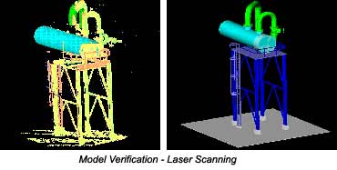
 Model verification and quality assurance ensure the accuracy of the model; the position, orientation, and size of the modeled components; and completeness of the model itself. This process consists of a series of model reviews or "walk-throughs." The completed computer model is overlaid on the high-resolution stereo photos and cloud of points at the graphics workstation to visually verify each of the quality assurance parameters.
In addition to the visual overlay verification, the software contains an expert subsystem that has the ability to analyze the clouds of points and stereo photos. Visual measurement verification aids and accuracy deviation dialogs provide the user with statistics and information about model accuracy and areas where the potential for error exists. These steps ensure the delivered model meets or exceed the required level of accuracy initially specified for the project.
VII. Engineering, Simulation and Information Management(Back to Top)
The final step of the documentation process is the transfer of the generated model to the target CAD system for engineering, simulation and information management purposes. The completed laser scanning and photogrammetry model moves from the graphics workstation to the client's 3D CAD design system. There, users can add new designs to the model, confirm fit-ups, perform equipment removal studies, routing studies, construction process reviews, space envelopes, obtain precise measurements of the "as-built" condition of the facility, and plan operation and maintenance activities.
 Commercial CAD systems provide a powerful design environment with effective design and management tools when a detailed model of the existing facility is available. An alternative approach is to provide the full capability for importing new CAD designs into the browser of the laser scanning and photogrammetry physical database system. This hybrid system, integrating laser scans, photogrammetry images, survey data and new design provides an effective and efficient environment for documenting the ongoing modifications and plant activities in an existing facility.
Project engineers realize several direct and immediate benefits they use laser scanning and photogrammetry to document the "as-built" condition of their plant.
First, they slash the cost and time needed to perform site data collection. Traditional methods of performing site documentation require the use of several personnel to manually measure and sketch the as-built facility. The process is time consuming, frequently produces errors, and results in minimal amounts of useful field data being collected and shared.
The methodology outlined in this paper, on the other hand, collects large volumes of very accurate and complete information. The process is more efficient, costs about the same as the manual approach, and results in a single physical database where all engineers can extract plant geometry and information through a browser. The same data can be used to create accurate CAD models that can be manipulated, analyzed, and used extensively in revamp/retrofit projects and/or plant operation and maintenance.
Other direct benefits of this integrated process include:
INOVx Solutions provides visualization solutions for plant documentation and information management. The company employs a proprietary combination of photogrammetry and laser scanning technologies to produce scalable, fit-for-purpose databases and models of a plant's "as-is" physical condition.
For more information: Moh Hashemi, Ph.D., P.E., President, INOVx Solutions, 18011 Sky Park Circle, Ste. K, Irvine, CA 92614. Phone: 949-250-6524 (or 877-994-6689). Fax: 949-250-6526. Email: mhashemi@inovx.com.