Computer Systems Validation Pitfalls, Part 3: Execution Inconsistencies
By Allan Marinelli and Abhijit Menon

When work is not performed according to protocol instructions — by cutting corners on quality outputs with the focus on profit as the main driver or by creating unnecessary work that reduces efficiency – this can result in pharmaceutical, medical device, cell & gene therapy, and vaccine companies losing profits, efficiencies, and effectiveness. The reason is a lack of QA leadership and management/technical experience, among other poor management practices, coupled with the attitude that “Documentation is only documentation; get it done fast and let the regulatory inspectors catch us if they can find those quality deficiencies during Phase 1 of the capital project and our validation engineering clerks will correct them later”. Consequently, these attitudes can lead to at least 15 identified quality deficient performance output cases during the validation phases, as will be discussed in this four-part article series. See Part 1 and Part 2 of this series for previous discussion.1,2
In Part 3 of this article series, we will examine the following quality deficiency performance output cases (execution inconsistencies) we have observed, including unnecessary “generation of a deviation,” that waste execution efficiencies by not putting enough time where it matters:
- A technically inexperienced senior global QA requests a protocol deviation instead of accepting the comment “as is”.
- Inconsistent documentation upon executing the “Utilities Verifications” section/attachment of the protocol.
- The execution results stipulated in the output (Actual Result column) do not consistently match the corresponding evidence record.
We’ll use real case studies to illustrate our points.
A Technically Inexperienced Senior Global QA Requests A Protocol Deviation Instead Of Accepting the Comment “As Is”
Company ABC attempted to endorse a distributed manufacturing (DM) approach over and above the family approach across multiple sites during a large-scale phase 1 of the capital project. (The family approach was discussed in Part 2 of 4 of this article series.) One must be cognizant of abiding by your own approved procedures, work instructions, validation plans, test plans, test-scripts, quality management systems (QMS) directives, and any of the software development life cycle (SDLC) documentation requirements through a combination of agile methodology, good automated manufacturing practices (GAMP 5 Editon 2), and other applicable industry standards.
The definition of DM per the U.S. FDA is as follows: “a decentralized manufacturing strategy with manufacturing units that can be deployed to multiple locations”3and “Possible use scenarios include:
- Units located within manufacturing facilities operating within the host’s pharmaceutical quality system (PQS).
- Units manufactured and installed to the same specifications at multiple manufacturing facilities, networked and operated by a central remote PQS.
- Units as independent manufacturing facilities, each with its own PQS.”4
Irrespective of the approaches intended to be used to enhance manufacturing efficiencies, when there is a lack of experienced QA technical management leadership (regardless of the number of years they have worked in the industry), this creates problems.
In our experience as consultants, many times, the leadership personnel do not have much experience approving technical computer system validation (CSV) protocols for the capital project, entailing complex computerized systems such as ERP, BAS, MES, Delta V, Syncade, OSIsoft (Pi, BES, MES, etc.), etc.
We have seen an inexperienced global senior QA in this position violate their own protocol’s procedure and acceptance criteria by leading the team to generate an unnecessary deviation affecting multiple sites, establishing an unnecessary risk for the team to take additional time to complete the four proposed corrective actions delineated in the deviation. The deviation in question below is with respect to the building automation system (BAS), as an example that is indicated in screenshots 1 to 5.
NOTE 1: Screenshots 2 to 5 represent the metadata supporting the deviation with relevance to screenshot 1 and are depicted in this article for the readers’ easier understanding of connecting the dots.
NOTE 2: Transcribing a comment at the bottom of the page for screenshots 2 to 5 during the execution phase of the validation protocol was in congruence with the stipulations of the acceptance criteria by the validation engineer with a superscript 1 that further substantiates not needing to generate a deviation in the first place.

Figure 1: Screenshot 1 (The deviation was requested to be generated by the inexperienced senior global QA for minor protocol generation errors of the BAS system)
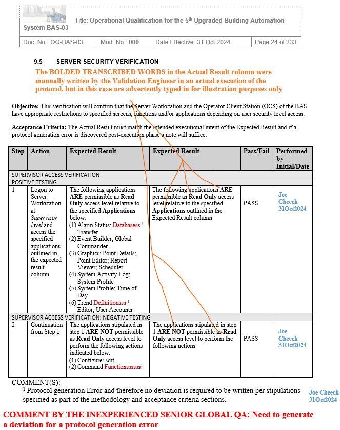
Figure 2: Screenshot 2 (Relevant to section 9.5 of the deviation)
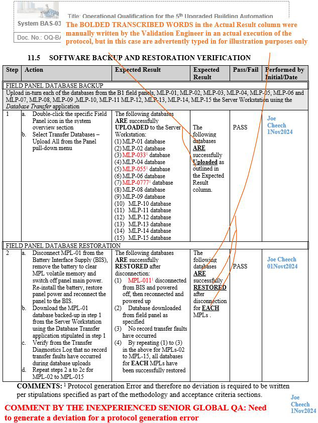
Figure 3: Screenshot 3 (Relevant to section 11.5 of the deviation)
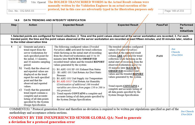
Figure 4: Screenshot 4 (Relevant to section 14.5 of the deviation)
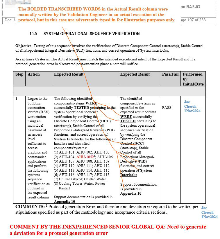
Figure 5: Screenshot 5 (Relevant to section 15.5 of the deviation)
Inconsistent Documentation Upon Executing The “Utilities Verifications” Section/Attachment Of The Protocol
Upon receiving numerous executed attachments as part of the protocol during the review post-execution phase, it was observed by the technically experienced senior QA that numerous validation engineers who executed the protocol test scripts and attachments for the same equivalent family approach CSV systems performed the execution in various inconsistent ways of not meeting the requirements (gaps), as shown in Scenarios 2 and 3, respectively, while Scenario 1 displays the correct/expected way that Attachment 2 was intended to be executed.
NOTE: The following legend corresponds to the significance of the F and D codes populated in the Actual Source column.

Scenario 1 (Correct methodology accompanied by a supporting comment): Attachment 2, Utilities Verification
Refer to screenshot Figure 6 below. The orange bold text on the upper portion of the image explains the rationale pertaining to the information transcribed in the Actual Attribute column, Actual Source column, and Meets Acceptance Criteria (Pass/Fail) column
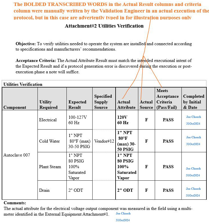
Figure 6: Scenario 1
Scenario 2 (Ambiguous inconsistencies on how the table was populated): Attachment 2, Utilities Verification
Refer to screenshot Figure 7 below.
- The orange bold text on the upper portion of the image explains the rationale pertaining to the information transcribed in the Actual Attribute column, Actual Source column, and Meets Acceptance Criteria (Pass/Fail) column.
- The green bold text on the upper portion of the image delineates the comment that was provided to the validation engineer during the review phase of the execution.
- The red bold text at the bottom portion of the image delineates the comment generated by the technically experienced senior QA for the reader to be aware of such inconsistencies during the execution phase.
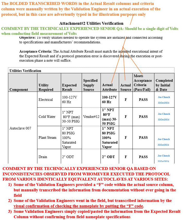
Figure 7: Scenario 2
Scenario 3 (Ambiguous inconsistencies on how the table was populated): Attachment 2, Utilities Verification
Refer to screenshot Figure 8 below.
- The orange bold text on the upper portion of the image explains the rationale pertaining to the information transcribed in the Actual Attribute column, Actual Source column, and Meets Acceptance Criteria (Pass/Fail) column.
- The red bold text at the bottom portion of the image delineates the comment generated by the technically experienced senior QA for the reader to be aware of such inconsistencies during the execution phase.
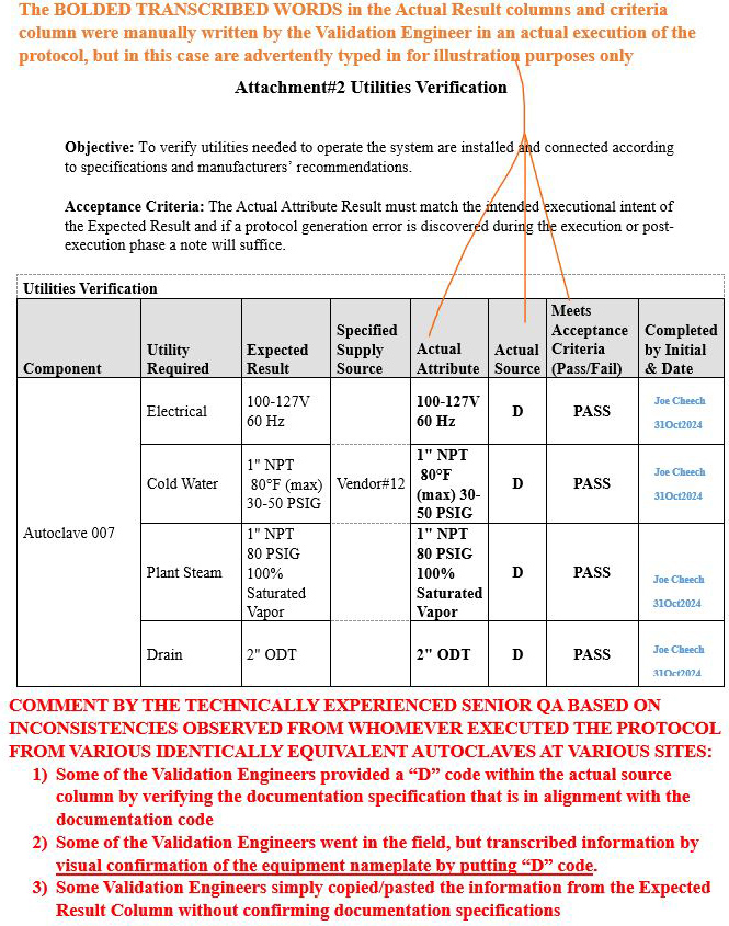
Figure 8: Scenario 3
Solution
Always ensure that any execution performed is aligned with the completed intended training, instructions, acceptance criteria, and relevant signatures and, if unsure, rather than attempting to rush the execution without understanding the intent of the attachment, confirm with experienced senior validation engineers who may be able to help or communicate with a hands-on technically experienced senior QA.
The Execution Results Stipulated In The Output (Actual Result Column) Do Not Consistently Match The Corresponding Evidence Record
Upon numerous QA reviews conducted by the experienced technical senior QA, it was observed as a gap pattern that the evidence (printouts) compiled and performed by the validation engineer during the execution phase provided some wrong evidence records in the respective appendix. This occurred despite the fact that the provided printout (evidence) was intended to meet the required specification parameters or system being validated for its intended uses, and did not always align with the stipulations in the Expected Result column for that executed step, even though the previous inexperienced senior QA was subsequently replaced with another inexperienced senior global QA. During their 25+ years in the industry serving in regulatory affairs management with a law degree, they had approved all of their 100+ executed protocols in this fashion without providing any respective comments, while turning a blind eye where it mattered.
As a result, at least three gap scenarios that were previously final QA approved by the aforementioned inexperienced senior global QA on other systems, such as manufacturing execution systems (MES), were repeated during the execution of the Programmable Logic Controller (PLC) Functional Test for Water For Injection (WFI) Module, but, fortunately, the experienced technical senior QA was able to subsequently identify such gaps upon their thorough QA review.

Figure 9: Scenario 1 (Wrong evidence printout provided in the appendix for the specified parameters shown in red): Attachment 40, Programmable Logic Controller (PLC) Functional Test for Water For Injection (WFI) Module
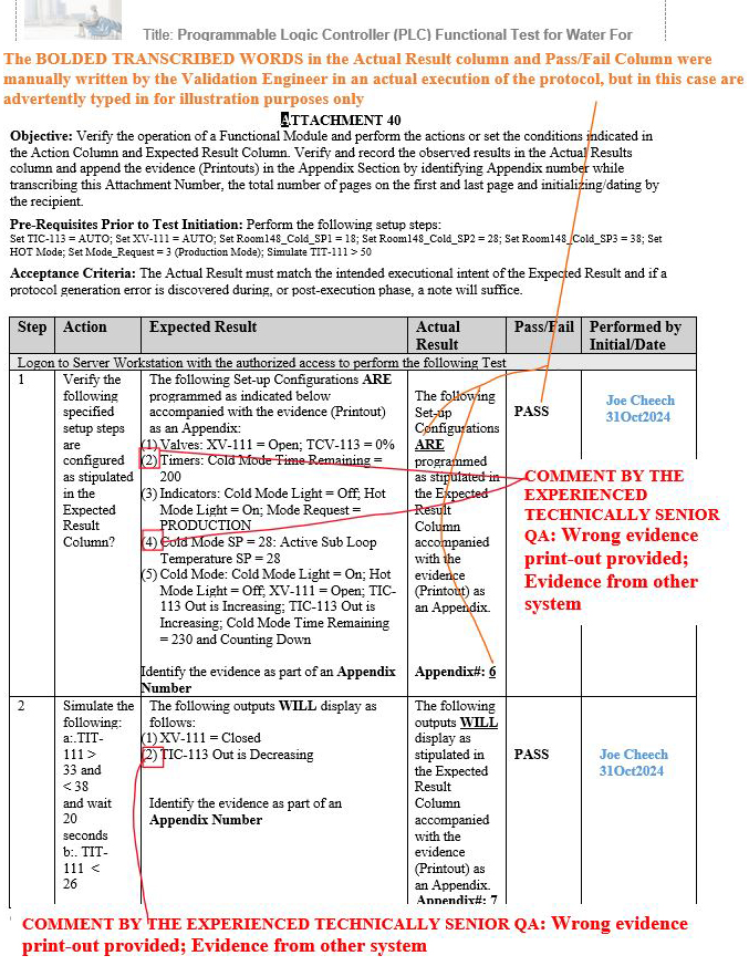
Figure 10: Scenario 2 (Wrong evidence printout provided in the appendix for the specified parameters shown in red): Attachment 40, Programmable Logic Controller (PLC) Functional Test for Water For Injection (WFI) Module
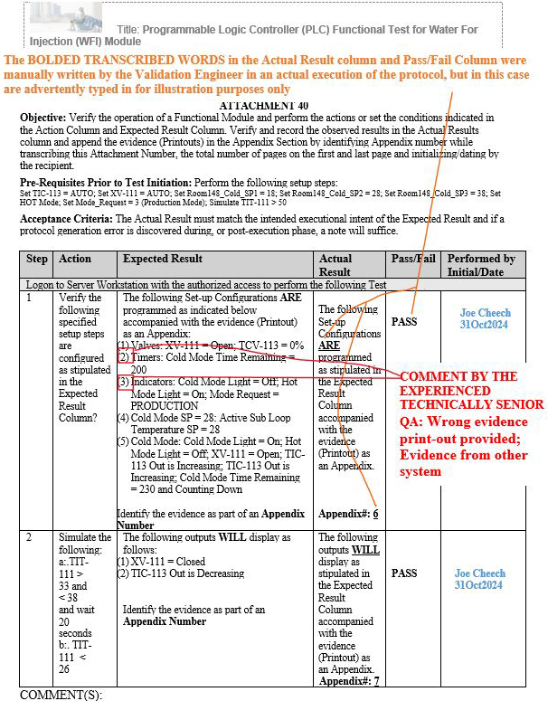
Figure 11: Scenario 3 (Wrong evidence printout provided in the appendix for the specified parameters shown in red): Attachment 40, Programmable Logic Controller (PLC) Functional Test for Water For Injection (WFI) Module
Solution
Always ensure that all the evidence provided as part of the support documentation within the appendices matches the intended requirements/parameters stipulated in the Expected Result columns.
Conclusion
QA managers need to show an example of great technical QA leadership by not approving inconsistencies and by not violating prescribed procedures accompanied by their respective acceptance criteria. QA managers must avoid the myopic vision of only meeting unreasonable projected schedules, as reworks will inevitably follow.
In Part 4 of this article series, we will discuss:
- incomplete metadata upon generating a family approach deviation
- pre-approving protocols for execution using the rubber-stamping methodologies (previously mentioned in Part 2 for the execution phase)
- no support documentation to substantiate the metadata stipulated in the expected result section
- Final Report Issue Scenario 1: incorrectly documenting the wrong deviation numbers in the result section of the final report (identified wrong deviation numbers in the compiled results table)
- Final Report Issue Scenario 2: created an additional incorrect identification of deviation number upon post- initial first QA review
- Final Report Issue Scenario 3: re-identified the initial wrong deviation number while identifying a nonexistent deviation number after a third QA review
References
- Computer Systems Validation Pitfalls Part 1 Methodology Violations
- Computer Systems Validation Pitfalls Part 2 Misinterpretations Inefficiencies
- CDER’s Framework for Regulatory Advanced Manufacturing Evaluation (FRAME) Initiative | FDA
- Distributed Manufacturing and Point of Care Manufacturing of Drugs
About The Authors:
 Allan Marinelli is the president of Quality Validation 360 Incorporated and has more than 25 years of experience within the pharmaceutical, medical device (Class 3), vaccine, and food/beverage industries. His cGMP experience has cultivated expertise in computerized/laboratory system, validation/information technology, quality assurance engineering/operational systems, compliance, remediation and validation roles controlled under FDA, EMA, and international regulations. His experience includes commissioning qualification validation (CQV); CAPA; change control; QA deviation; equipment, process, cleaning, and computer systems/laboratory validation; artificial intelligence (AI) software driver quality management systems; quality assurance management; project management; and strategies using the ASTM-E2500, GAMP 5 Edition 2, and ICH Q9 approaches. Marinelli has contributed to ISPE baseline GAMP and engineering manuals by providing comments/suggestions prior to ISPE formal publications.
Abhijit Menon is a professional leader and manager in senior technology/computerized systems validation while consulting in industries of healthcare pharma/biotech, life sciences, medical devices, and regulated industries in alignment with computer software assurance methodologies for production and quality systems. He has demonstrated his experience in performing all facets of testing and validation including end-to-end integration testing, manual testing, automation testing, GUI testing, web testing, regression testing, user acceptance testing, functional testing, and unit testing as well as designing, drafting, reviewing, and approving change controls, project plans, and all of the accompanied software development lifecycle (SDLC) requirements.
