
Evaluating The Container Closure Integrity Of A Vial Using Headspace Gas Ingress Methods
By Allison Alix, Application Scientist at Lighthouse Instruments

To ensure patient safety, pharmaceutical products must be kept properly packaged prior to use. Proper packaging prevents ingress of contaminants, including microbes and degradational gases, that can potentially alter the properties and functions of the drug. Unfortunately, these contaminants are not always visible to the human eye, and auxiliary tests, known as container closure integrity (CCI) tests must be performed to ensure the package has not been compromised. One way to test for proper CCI is to analyze the headspace gas composition of the vial.
Laser-based headspace gas analysis is a deterministic CCI test method recommended by USP <1207> which can be used to quantify gas ingress into a parenteral package containing defects1, 2. Generally, during measurement of a sample, an NIR laser is tuned to the vibrational frequency of a target gas molecule and directed through the vial headspace (i.e. the region above the product). As the laser light passes through the headspace, a portion is absorbed by the target gas molecules. This technique is more specifically known as frequency modulation spectroscopy, or simply FMS. The area and width characteristics of the resulting FMS absorption signal provide information about the target molecule number density and/or pressure (Figure 1). Because pharmaceutical products are often packaged at specific headspace conditions, this headspace gas analysis technique is an attractive method for CCI testing.
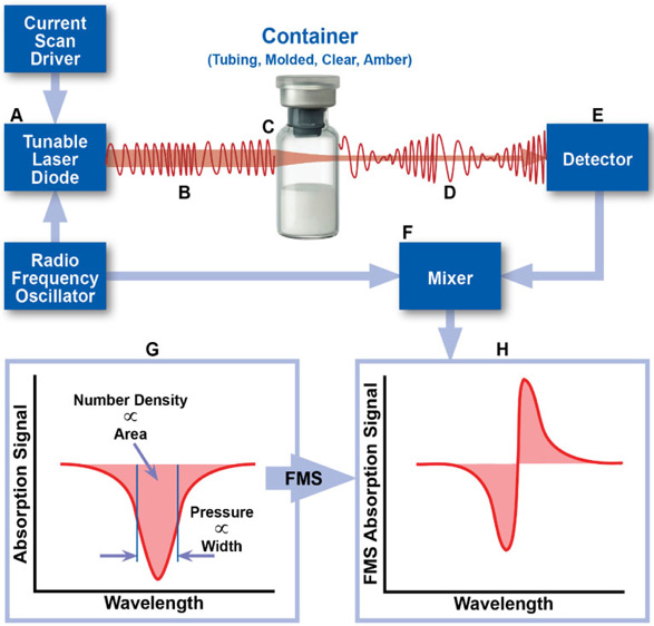
Figure 1. Schematic overview of the measurement technique. The area and width of the FMS absorption signal can be used to determine physical parameters of the headspace of a container, including gas number density and total pressure.
In order for FMS to be used as a CCI test method, the potential for gas exchange to occur between the vial headspace and its surrounding environment must exist. One way to ensure this gas exchange occurs (providing a defect is present in the vial) is to place the sample in a pressure vessel and expose the sample to a tracer gas environment. Because very little carbon dioxide is found at ambient conditions, carbon dioxide is a reliable option for the tracer gas. Using carbon dioxide also allows for vials packaged under atmospheric conditions to be tested, as you would not initially expect any carbon dioxide to be present in the vial. This means that even small increases in carbon dioxide can be used as a marker for integrity failure. This method is very similar to the probabilistic blue dye ingress method in concept but has the significant advantages of being rapid, non-destructive, and analytical. The following case study applies this methodology to 15R vials packaged under air.
CASE STUDY:
Two types of defects intended to represent “real-world” scenarios were explored: laser-drilled defects located in the glass body of the vial, and defects located at the stopper-seal interface created by placing a tungsten microwire across the landing seal. Note that the outer diameter of the microwire is not representative of the defect size as the compressed rubber stopper will flow and partially seal around the wire. However, using a vacuum decay leak rate apparatus3, the flow effective diameters of the microwire defects were estimated as 2.0, 6.1, and 8.5 μm for the 41, 64, and 80 μm wires, respectively, using their measured leak rates and Table 1 of USP 40 <1207.1> Section 3.9.
Three different sets were prepared for each of the defect types and sizes: an empty set, a set filled with 5mL PBS, and a set filled with 5mL of a solution of BSA in PBS (1mg/mL). For the laser-drilled defects, the fill covered the laser-drilled hole. For the micro-wire defects, the vials were inverted three times prior to performing the CCI test to ensure the fill came into contact with the defect. For these formulation filled vials, the carbon dioxide tracer gas would be required to overcome the surface tension associated with the liquid surface at the defect site before reaching the headspace. The tracer gas overpressure needed to overcome this surface tension increases with decreasing defect size. Furthermore, protein-based solutions have the potential to clog the defect site when coming into contact with it, making them more difficult to detect. The results of filled positive controls were compared to CCI test results of the empty positive controls.
Figure 2 and Figure 3 show the carbon dioxide content measured in the laser-drilled vials and micro-wire vials, respectively. A Lighthouse Instruments FMS-Carbon Dioxide Headspace Analyzer was used to acquire the headspace measurements. There was no significant carbon dioxide initially present in any of the vials (T0), consistent with ambient conditions.
After placing all vials in the pressure vessel and exposing them to carbon dioxide at 20 psig (34.7 psia) for 30 minutes, the resulting T1 measurements were obtained. All empty vials were detected as having carbon dioxide in them except for the negative controls (as expected). Not surprisingly, no carbon dioxide was observed in the filled 2 μm laser-drilled vials or in the filled 41 μm wire vials, due to the potential complications with liquid fills described above. It should be noted that these defect sizes do not represent the limit of detection of the methodology but are heavily dependent on both the vial configuration as well as the product. Ultimately, both the overpressure and hold time can be easily adjusted to be able to identify the desired defect size for a particular product-vial configuration.
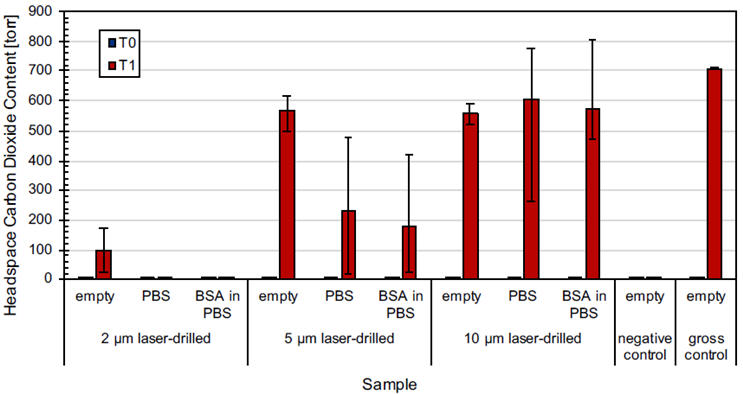
Figure 2. Headspace carbon dioxide content before (T0) and after (T1) performing the CCI Test on laser-drilled vials that were empty, filled with PBS, and filled with 1 mg/mL BSA in PBS. Values show the averages of five measurements on ten laser-drilled vials for each defect size and fill and five measurements on three vials for the negative controls and gross positive controls. Error bars show the min max range across the averages for each sample set.
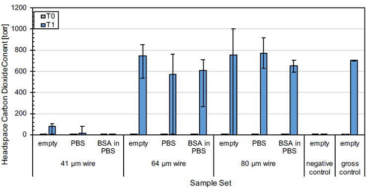
Figure 3. Headspace carbon dioxide content before (T0) and after (T1) performing the CCI Test on the various control vials. Values show the averages of five measurements on five vials for each wire size and fill and five measurements on three vials for the negative controls and gross positive controls. Error bars show the min max range across the averages for each sample set.
REFERENCES:
- The United States Pharmacopeia, Package Integrity Evaluation – Sterile Products, Maryland, 2016.
- Victor, K. G.; Levac, L; Timmins, M.; Veale, J. Method Development for Container Closure Integrity Evaluation via Headspace Gas Ingress by Using Frequency Modulation Spectroscopy. PDA J Pharm Sci Tech, 2017; 71(6), 429-453.
- Alix, A. K.; Victor, K. G.; Timmins, M.; Veale, J. Container Closure Integrity Test Using Frequency Modulation Spectroscopy Headspace Analysis with Carbon Dioxide as a Tracer Gas. PDA J Pharm Sci Tech, Submitted.