
Handling & Processing Of Potent Compounds: A Holistic Approach
By Herman F. Bozenhardt, Bozenhardt Consulting Services, and Erich H. Bozenhardt, IPS-Integrated Project Services
 The topic of potent compounds may seem obscure; however, it touches virtually every aspect of the biopharmaceutical business, from selection pressure in media to antibody-drug conjugates (ADCs). Every chemical and biological compound we work with has an MSDS (material safety data sheet) and an OEL (occupational exposure limit), which dictate how we must handle the compound and bring to the forefront the issues of personnel safety and environmental impact that we must address in our manufacturing plants. When designing a process involving any potent compound, there are three aspects we must address directly: facilities, processing equipment, and people.
To begin with a definition, potent compounds are any materials that can cause chemical, physiological, or physical harm to humans or the environment. These can be compounds used in oncology, opioids, certain vaccines and their components, neurological drug substances, cytotoxic materials, cosmetic components, and organic chemicals (e.g., USP nicotine). The FDA recognizes the need for specialized handling of such compounds, and refers to it in 21 CFR 211; and the ICH (International Conference on Harmonisation of Technical Requirements for Registration of Pharmaceuticals for Human Use) discusses it in ICH Q7A. In addition, NIH, EPA, OSHA, and NIOSH (The National Institute for Occupational Safety and Health) have specific instructions and guidelines. Finally, the International Society for Pharmaceutical Engineering (ISPE) provides design guidelines, such as ISPE SMEPAC (Standard Measure of Equipment Particulate Airborne Concentration)1 for these applications.
The first step in understanding the handling of any potent compound is finding out the key safety and health parameters of the material:
- Occupational exposure limit (OEL)/permissible exposure limit (PEL)
- Long-term and short-term exposure limits (LTEL/STEL)
- Special considerations (e.g., hormone, sensitizer, gender-biased effects)
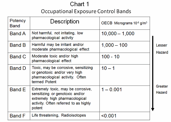
Occupational exposure bands (OEBs) provide an easy way of bringing the different aspects of a compound’s toxicity together and reaching a control solution. There are many different banding schemes in use in the industry. The banding schemes relate a compound’s toxicity to effective engineering/operational controls. OELs can be calculated by various methods: No-effect limits, therapeutic dose, and incremental endogenous biological activity are frequently used. However, these calculated limits may not account for sensitization or carcinogenic effects. In several banding schemes, compounds that have such special considerations must be handled in accordance with the next higher band or at a minimum band level. As an example, a material with an OEB value of between 100 and 10 micrograms per cubic meter is a B and C material, and requires specially designed containment.2 All materials with an OEB value less than 10 micrograms per cubic meter (Bands D, E, and F) present serious requirements (see Chart 1).
The next step is understanding the process completely and analyzing the following:
- What are the weights, volumes, and flow characteristics of the materials and products?
- How do the operators control the equipment, and do they perform interventions? If so, how often?
- How and when are samples taken and processed by QC?
- How is the material subdivided and packaged, and where is that done?
- How are the equipment and processing rooms cleaned?
- What happens when the equipment needs to be maintained, and how is it prepared for repair?
- How are the materials transported through the facility, and exactly how is waste contained and removed?
The answers to these questions should pinpoint the life cycle and physical route of the potent compound in the facility: where it is exposed, where it is handled, and in what quantity.3 When this analysis is completed, each of the following questions should be answered for each step of the process:
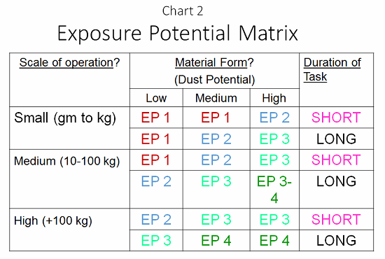
- In what form is the compound, and what is its ability to disperse (e.g., a fine dust, with high ability to disperse; a granular powder, with medium ability; or a wet paste, with low ability)?
- For what duration will the operator have to work with the material (short time — less than 30 minutes, or long time — more than 30 minutes?
- What is the scale of the process: small (grams to 1 kg), medium (10 to 100 kg), or large (greater than 100 kg)?
Armed with this information, and aided by a tool called the exposure potential matrix (EPM; see Chart 2), a robust risk assessment can be provided. At each process step, an EPM value of 1 to 4 must be provided to determine the potential exposure. At this point, effort can be made to reduce the exposure through selection of containment methods with the equipment, providing a better facility around the process and protecting the personnel. Put another way, the EPM is a direct reflection of the risk of exposure to an operator, or a risk assessment of the process based upon the physical attributes of the manipulation of the material.
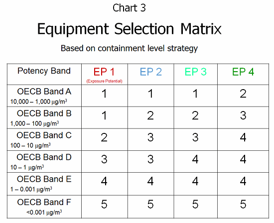
Given the previous EPM value and knowing the OEB band (level of toxicity) allows a clear understanding of the risks and potential harm that are present. Through the ESM (equipment selection matrix; see Chart 3), this risk information can be combined into a mechanism for selecting the containment approach. This overlays the risk of exposure with the known toxicity of the compound to provide a design criteria for operator protection. Containment level design strategies 1 through 5 can be summarized as follows:
- Level 1 — General ventilation supporting the operator, dispensing room, basic operator tools
- Level 2 — Local exhaust ventilation directing airflow away from operator, dispensing room, mask/gloves
- Level 3 — Barrier system with dust collection/exhaust, dedicated dispensary, gowned operator
- Level 4 — Closed handling with isolator glove ports/negative pressure room, gowned operator
- Level 5 — Robotic handling with no human contact, specialized docking/isolator receiving system
Once the containment approach has been developed, the three design aspects of facility, processing equipment, and operator assistance must be addressed directly. As a general guideline, beginning at Level 2, there must be one level of contained separation between the operations personnel and the material of concern for each additional level. Therefore, at Level 3, there are two design features, such as a barrier and an exhaust system in a dedicated space, and gowned personnel with PAPRs (powered air purifying respirators). At Level 4, there is an isolator in a designated space, negative pressure HVAC (heating, ventilation, and air conditioning), and gowned personnel with PAPRs.
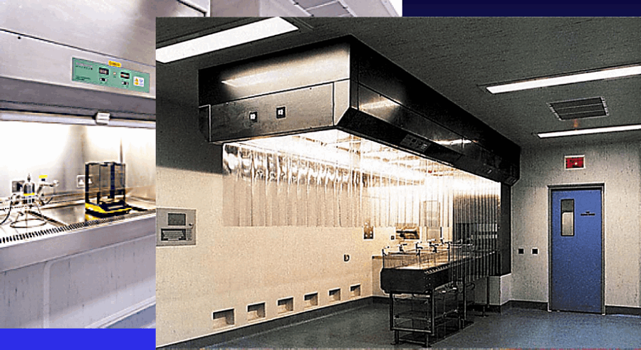
Figure 1: Level 1 containment example
Facilities
One of the key questions the designer must consider is how to isolate and dedicate a suite for all the potent compound manipulation and processing, which includes dispensing, processing, packaging, and cleaning. For Level 3 and above, this means building a self-contained “plant within a plant.” This allows for a single point of cleaning, decontamination, and maintenance, where the operational rules are focused on the material hazards, and possible cross-contamination with other products is eliminated. Such cross-contamination can have many sources, but often is the product of normal personnel flow, thus the facility modifications that must be implemented focus on personnel support. Among these are:
- Dedicated locker rooms with separate entrances and exits from the existing plant
- Separate gowning and de-gowning rooms to minimize the potential contamination of personnel’s street clothes
- Unit operations in one room with appropriate airlocks for EU grades, plus one additional “air sink” before the process room entry and exit
- Single-suite design, arranging all processes in sequence within a single suite, and designs of equipment to be integrated, thus minimizing transfers
- Sufficient utility capacity that provides all process needs within the single suite, including CIP (clean in place)
- Dedicated liquid waste drains and downstream processing from CIP or COP (clean out of place)
- HEPA in/HEPA out (HEPA = high-efficiency particulate air) for the suite to prevent potential contamination of the HVAC system, and installing a BIBO (bag in/bag out) unit for the HEPA returns inside the contained suite for change out
- Containment HVAC that provides a negative pressure gradient across the facility from the outer CNC (controlled not classified) area into the processing suite, to prevent the potent compound from exiting the facility
- Redundant HVAC AHUs (air-handling units) to assure the potent compound does not leave in an airstream if one AHU should fail.


Figure 2a and 2b: Level 2 containment examples
Process Equipment Engineering
From a processing standpoint, it is necessary to take a close look at the equipment and understand it from a material transfer, exhaust, and cleaning perspective. Below are some of the process features that must be incorporated into the design approach:
- Isolation technology — using glove box system/isolator system to handle all product transfers, including dispensing, sample taking, equipment adjustment, cleaning, and container manipulation
- Dust, liquid, and gas exhaust systems to trap, collect, and contain the effluent in a disposable bag
- Closed transfer systems with double butterfly valves. These have been adapted for many applications and are the standard in the industry for all interfaces between equipment. These are built into drum transfer systems, IBC (intermediate bulk container) containment transfer systems, and powder transfer systems.
- Vertical systems of equipment to prevent floor penetrations, and incorporating charging stations in a gravity feed scenario, providing integrated processing steps
- Single-use systems/disposables. These are now the most focused part of processing, with flexible, disposable isolators for dispensing, disposable pallet tanks for processing and mixing, and disposable transfer systems and connectors for interface to traditional steel equipment. The process engineer today can source a substantial amount of the process equipment as disposables and thus eliminate cleaning.
The maintenance of these systems must also be addressed when selecting equipment. All the drive components, motors, electrical, and gears must be in a sealed, pressurized compartment, or preferably in a “gray space” external to the processing room. This will allow maintenance to be performed without having to expose the mechanics to the potent compounds.

Figure 3: Level 3 containment example
Last but not least, a major area in the process space is the waste collection, containment, and neutralization area. These drain systems must be dedicated, provide a dedicated collection and neutralization container, and be periodically pumped out, with the waste removed to a hazardous waste site. There must also be a provision for sample taking.
Operator Protection
The final design consideration is operator protection. The level of operator protection must take into account that one of the barriers or levels of protection designed for the process equipment could fail or be compromised. This assumption, combined with the pharmaceutical gowning level, typically requires operators to use a full gown/gloves/mask at Level 2, and full gown/double gloves/hood/PAPR system at Levels 3, 4, and 5. The requirement for PAPR can be reconsidered after exposure data is collected during routine operations.

Figure 4: Level 4 containment examples
Overall, the design considerations for potent compound handling require a critical understanding of the particular potent compound involved and the process being executed. These, in turn, determine the exposure potential and dictate how to design to eliminate the exposure, minimize waste, and protect the operators. As pharmaceutical engineers, we are ultimately in charge of personnel protection, that is, minimizing personal injury and harmful ingestion/inhalation of potent compounds.
References
- ISPE Good Practice Guide: Assessing the Particulate Containment Performance of Pharmaceutical Equipment, Standardized Measurement of Equipment Particulate Airborne Concentration (SMEPAC) Committee, http://www.ispe.org/publications-guidance-documents/assessing-particulate-containment-performance
- Nigel Hirst, Mike Brocklebank, Martyn Ryder (Eds.), Containment Systems: A Design Guide, IChemE (2002). ISBN 0 85295 407 7.
- Gary Q. Johnson, P.E., “Process Containment Design — Just Enough to Meet the Need!,” The Great Lakers Press, The Newsletter of the ISPE Great Lakes Chapter, Vol. 11, No. 2, Fall 2005, pp. 9-15.
About The Authors:
 Herman Bozenhardt has 41 years of experience in pharmaceutical, biotechnology, and medical device manufacturing, engineering, and compliance. He is a recognized expert in the area of aseptic filling facilities and systems and has extensive experience in the manufacture of therapeutic biologicals and vaccines. His current consulting work focuses on the areas of aseptic systems, biological manufacturing, and automation/computer systems. He has a B.S. in chemical engineering and an M.S. in system engineering, both from the Polytechnic Institute of Brooklyn.
 Erich Bozenhardt is the process manager for IPS-Integrated Project Services’ process group in Raleigh, NC. He has 11 years of experience in the biotechnology and aseptic processing business and has led several biological manufacturing projects, including cell therapies, mammalian cell culture, and novel delivery systems. He has a B.S. in chemical engineering and an MBA, both from the University of Delaware.
Image credit: Charts are courtesy of Howorth Pharma and Paul Egee.