
Interpreting The New ASME/BPE-1997 Guidleines For High Purity Ball Valves For Pharmaceutical Applications.

What is a High Purity ball valve?
High Purity ball valves are flow control devices that meet the industry criteria for purity of materials and design. Valves in high purity processes are used in two broad areas of application:
- Valves that are in direct contact with the final (or intermediate) product
- Valves that are not in contact with the final (or intermediate) product.
These applications are in "support systems" such as handling clean steam for cleaning and temperature control. In the pharmaceutical industry ball valves are never used in applications or processes where they may be in direct contact with the final product.
What are the industry criteria for high purity valves?
The pharmaceutical industry derives the valve selection criteria from two sources:
- ASME/BPE-1997 (Specifications for Bioprocessing Equipment)
- FDA material and design specifications
ASME/BPE-1997 is the evolving specification document that addresses the design and use of equipment for the pharmaceutical industry. The standard is intended for design, materials, construction, inspection and testing of vessels, piping and related accessories such as pumps, valves, and fittings for use in the biopharmaceutical industry. Essentially the document states, "…all parts that contact either the products, raw materials, or product intermediates during manufacturing, process development, or scaleup...and are a critical part of product manufacture, such as Water-For-Injection (WFI), clean steam, ultrafiltration, intermediate product storage, and centrifuges."
Today, the industry relies on ASME/BPE-1997 to determine ball valve designs for use in applications where they are not in contact with the product. The key areas covered by the specification are:
Materials
- body materials
- seat materials
- welded component materials
- stem seals
- end connections
Surface Condition
- mechanical polishing
- electro-polishing
- surface finish
Drainability
- Valve design for minimum hold-up volume
- Installation angles
Valve Applications
- Clean steam
- WFI-Water For Injection
- Ultrafiltration
- Gas Delivery
- CDA-Clean Dry Air
- High Purity Water
- Alcohol
Material Composition
- 316L
- Sulfur content
- Certification (MTR's, FDA etc.)
Inspection
- Cleanability
Marking Information
What valve types does ASME/BPE address?
Valves typically used in bio-pharm process systems include ball, diaphragm and check valves. This engineering document will be limited to discussions on ball valves.
What is "validation"?
Validation is a regulatory procedure that intends to assure repeatability of a processed product or formulation. The procedure indicates that mechanical process components, formulation times, temperatures, pressures and other conditions be measured and monitored. Once a system and the product of that system have proven repeatable all components and conditions are deemed validated. No changes may be made to the final "package" (process system and procedures) without re-validating.
There is also the related issue of material verification. MTR's (Material Test Report) is a statement from casting producers that documents the composition of the casting and verifies that it has come from a specific run in the casting process. This degree of traceability is desirable in all critical piping component installations in many industries. All valves supplied for pharmaceutical applications must be accompanied by MTR's.
Seat material manufacturers provide a composition report to ensure that valve seats meet FDA guidelines. (FDA/USP Class VI) Acceptable seat materials include PTFE, RTFE, Kel-F and TFM.
What industries/systems use High Purity ball valves?
- Bio-Pharm
- Pharmaceutical
- Food / Beverage
- Semiconductor
- Cosmetics
- Gas Delivery Systems
- Water Purification
- Brewing / Distilling
- Sterilization Systems
What is Ultra-High-Purity?
Ultra-High-Purity (UHP) is a term that intends to emphasize the need for extremely high levels of purity. It is a term widely used in the semiconductor marketplace where absolute minimal amounts of particles in the flow stream are demanded. Valves, piping systems, filters and many materials used in their construction often meet this UHP level when prepared, packaged and handled under specific conditions.
What standards are used in the semiconductor industry for High Purity ball valves?
The semiconductor industry derives valve design specifications from a compilation of information managed by the SemaSpec group. The production of microchip wafers requires extremely strict adherence to standards to eliminate or minimize contamination from particles, outgassing and moisture.
The SemaSpec standards detail sources of particles generation, particle size, sources of gasses (via soft valve components), helium leak testing and moisture from within and without the valve boundary.
Why does the High Purity market prefer to use ball valves in their systems?
Ball valves are well proven in the most rigorous applications. Some key advantages of the design include:
- Economical - compared to most other valve designs
- High flow rate through an unobstructed flow path
- Quick, quarter-turn operation
- Easy to automate pneumatically or electrically
- Inherently flexible to meet a wide range of pressures and temperatures
- Simple maintainability
- Self-flushing design
What is mechanical polishing? Electro-polishing?
Mechanical polishing – Mill finishes, welds and surfaces that have been in service have differing surface characteristics when viewed under magnification. Mechanical polishing reduces all surface ridges, pits and discrepancies to a uniform roughness.
Mechanical polishing is accomplished utilizing aluminum oxide abrasives on rotary equipment. Mechanical polishing can be achieved by hand held tools for large surface areas, such as reactors and vessels in place, or by automatic reciprocating machines for pipe or tubular components. A series of grit polishes is applied in a successively finer sequence until the desired finish or surface roughness is achieved.
Electropolishing is the electrochemical removal of microscopic irregularities from metal surfaces. It results in a general leveling or smoothing of the surface, that when viewed under magnification, appears virtually featureless.
As a result of electropolishing, a metal surface exhibits the following properties:
- Surface roughness is significantly reduced, thus reducing adhesion properties.
- Surface area is reduced as much as 7:1.
- Surface friction and drag are reduced.
- Corrosion resistance is increased due to a chromium enrichment of the surface and the removal of surface contaminants that may promote corrosion.
Stainless steel has a natural resistance to corrosion due to its high chromium content (stainless steels are typically 16% chromium or higher). Electropolishing enhances this natural resistance because the process dissolves more iron (Fe) than chromium (Cr). This leaves higher levels of chromium on the stainless steel surface. (Passivation)
How is surface finish measured?
The result of any polishing procedure is to create a "smooth" surface defined as the Roughness Average (Ra). According to ASME/BPE; "All polishes shall be referred to in Ra, micro-inch (m-in) or micro-meter (mm)."
Surface smoothness is generally measured with a profilometer, an automatic instrument with a stylus-type reciprocating arm. The stylus is traversed across a metal surface, measuring peak height and valley depth. The average peak height and valley depth is then expressed as a roughness average in terms of millionths of an inch –or micro inch, frequently referred to as Ra.
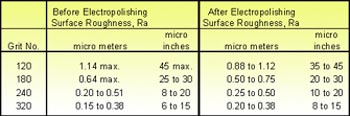
The relationship between polished and buffed mill finishes, abrasive grit numbers and surface roughness—before and after electropolishing—is illustrated in the following table. (For the ASME/BPE derivation see Table SF-6 in this document)
Micro meters is a common European standard, the metric equivalent to micro inches. One micro inch is equal to approximately 40 micro meters. For example: A finish specified as 0.4 micro meter Ra is equal to 16 micro inch Ra.
What fluids are typically handled by high purity ball valves?
Due to the inherent flexibility of the ball valve design, it is readily available in a wide range of seats, seals and body materials. As a result, ball valves are produced to handle fluids such as:
- Steam – process temperature control / cleaning
- High Purity Water – cleaning
- High Purity Gas – purging
- CDA (Clean Dry Air) – purging
- Alcohol – deliver alcohol to final product (cosmetics) / cleaning
When are valves selected with ETO or Tri-Clamp end connections? What other ends are used?
Whenever possible, the bio-pharm industry prefers to install "sealed systems". Extended Tube OD (ETO) connections are welded in-line to eliminate contamination from outside the valve/piping boundary and to add rigidity to the piping system. Tri-Clamp (Hygienic Clamp Connections) ends add flexibility to the system and may be installed without welding. With Tri-Clamp ends, piping systems may be disassembled and re-configured more readily.
High Purity systems (such as in the food/beverage industry) may also use Cherry-Burrell fittings branded under the names "I-Line", "S-Line", or "Q-Line".
ETO Explained
An Extended Tube OD (ETO) end is one that permits in-line welding of the valve into the piping system. The dimension of the ETO end matches the tubing (piping) system diameter and wall thickness. The extended tube length accommodates orbital welding heads and provides sufficient length to prevent body seal damage due to the heat of welding.
How do ball valves compare to diaphragm valves in piping/system design?
Ball valves are widely used in process applications because of their inherent versatility. Diaphragm valves offer a limited service range for temperature and pressure and do not meet all of the standards for industrial valves. Ball valves are available for:
- Cryogenic service
- High temperature / Low temperature
- High velocity / Low velocity
- High pressure / Low pressure
- Wider range of seat materials
- Wider range of body materials
- Wider range of end connections
- Fire-safe designs
In addition, ball valve center sections are removable to allow access to the inner weld bead where cleaning and/or polishing may then be performed.
What is drainability?
Drainability is important for maintaining bioprocess systems in a clean and sterile condition. Fluid remaining after draining becomes a colonization site for bacteria or other microorganisms creating an unacceptable bioburden to the system. Sites where fluid accumulates also may become a corrosion-initiation site adding additional contaminants to the system. The design Part of the ASME/BPE Standard calls for hold-up volume, or that amount of liquid which remains in the system after draining is complete, to be minimized by design.
What is "dead leg"?
A dead leg in a piping system is defined as a pocket, tee, or extension from a primary piping run that exceeds a defined number of pipe diameters (L) from the ID of the primary pipe (D). A dead leg is undesirable because it provides an area of entrapment which may not be reached by cleaning or sterilizing procedures and thus leads to contamination of the product. For bioprocessing piping systems an L/D ratio of 2:1 is considered to be achievable for most valve and piping configurations.
Where are fire-safe valves used?
Fire-safe valves are designed to prevent flammable fluids from spreading in the event of a process line fire. The design uses metal back-up seats and an anti-static feature to prevent ignition. The biopharmaceutical and cosmetics industries often prefer fire-safe valves in alcohol delivery systems.
What are the acceptable seat materials for High Purity ball valves?
FDA-USP23, Class VI approved seat materials for ball valves include; PTFE, RTFE, Kel-F, PEEK and TFM.
What is TFM?
TFM is chemically modified PTFE that fills the gap between conventional PTFE and melt-processable PFA. According to ASTM D 4894 and ISO Draft WDT 539-1.5, TFM is classified as a PTFE. Compared to conventional PTFE, TFM has the following enhanced properties:
- Much lower deformation under pressure (cold flow) at room and elevated temperatures.
- lower permeability
- May be used at higher pressures
What about cavity-filler seats?
Cavity-filler seats are intended to prevent the build up of materials that may –when entrapped between the ball and body cavity- solidify or otherwise inhibit the smooth operation of the valve closure member. High Purity ball valves used in steam service should not utilize this optional seat arrangement as the steam will find its way under the seat surface and become an area for bacterial growth. Due to this larger seating area, cavity-filler seats are difficult to properly sanitize without disassembly.
What actuators are available with ball valves?
Ball valves fall under the general category of "rotary valves". For automatic operation there are two types of actuators available: pneumatic and electric. Pneumatic actuators utilize pistons or diaphragms connected to a rotary mechanism, such as a rack and pinion arrangement, to provide rotary output torque. Electric actuators are basically geared motors and are available with a wide range of voltages and options to accommodate ball valves. For more information on this subject see "How To Select Actuators For Ball Valves" later in this manual.
List the typical options available with High Purity ball valves
End connections
- Extended Tube OD (ETO)
- Tri-Clamp / Hygienic Clamp
- "I"-Line
- "S"-Line
- "Q"-Line
Purge ports
- Compression
- VCR
- Tubing
Sampling Valve
- Ball or Diaphragm
- Select Location
Tank Bottom Design
- Flush Fit to Hoppers/Tanks
Multi-porting
- Various flow configurations
Lateral Valve Configuration
- For semiconductor installations
Fire-safe design
- Meets API-607 standards
Surface Finish
- Mechanical
- Electro-polishing (specify degree of finish)
What are the common cleaning procedures used with High Purity ball valves?
High Purity ball valves may be cleaned and packaged according to BPE or Semiconductor (SemaSpec) requirements.
Area & Equipment
- Cleaning is performed in a room segregated from the normal valve production area to eliminate contamination.
- The room is outfitted with one alkaline cleaning tank, a DI rinse tank and a hot air drying tank.
- Work areas are freshly covered with particle-free plastic sheeting before each cleaning.
- Bubble-tight valve testing equipment utilizes clean, dry, oil-free air.
- Capping and bagging is performed on the particle-free surface. All bags are 4 mil and are heat-sealed. Double bag option is available.
Cleaning Agent
The basic cleaning is performed using an ultrasonic cleaning system with an approved alkaline agent for cold cleaning and de-greasing in a residue-free formulation.
VOC emission level = 0
Procedure
- Each valve component is thoroughly washed in the cleaning agent tank then rinsed in a de-ionized water tank. The components are then dried in a hot air drying vessel.
- Valve assembly is performed in a Class 100 room on a particle-free surface using latex gloves. Clean, grease-free tools are used in the assembly of valves.
- After assembly the valves are nitrogen purged with 99.999% pure N2 filtered with 0.01 micron rated filters.
- The fully assembled valve is tested for leakage using clean, dry, oil-free air according to industry standards.
- Each valve is capped, bagged (4 mil) and heat-sealed to ensure product quality and purity until installed.
Packaging (Semiconductor / Pharmaceutical)
- Each finished (dry, completed, inspected and approved) end connector is covered with "clean" Aclar or Nylon film and then capped with non-shedding end caps – which do not come in contact with the inner surfaces.
- Each finished valve is bagged in 4 mil thick, clean polyethylene with a full filtered nitrogen (0.01 micron) purge, to prevent contamination. The bag is then sealed to provide a waterproof environment.
- Valves with sharp edges are additionally padded to prevent puncturing during shipment.
- Packaging is done in the same clean room where the cleaning procedure was performed. Components are not removed from the clean room until they are properly packaged and sealed.
- Valves are only removed from the clean room environment in sealed, non-shedding containers or with appropriately capped ends.
All valves are permanently marked with the following information.
- Manufacturer's name or logo
- Heat number on each component part of the fitting if more than one heat is used
- Material type
- Specification number referencing the BPE standard
- Internal surface symbol for the appropriate BPE specification
- Color coded handles if applicable.
Quality Assurance
Certificate of Traceability
Pressure-containing components are marked with heat numbers and backed by appropriate analysis certificates.
Mill Test Reports (MTR's) are recorded for each size and heat number. These documents include:
- Alloy- ASTM designation
- Heat number
- Year and month of manufacture
- Chemical analysis
- Mechanical properties
- Heat treatment
How to Select Actuators For Ball Valves
At times it is necessary for a process engineer to choose between a pneumatically or electrically actuated valve for a process control system. There are advantages to both styles of actuators, and it is valuable to have data available to make the best choice.
Compatibility (Power Source)
First and foremost in the selection of an actuator type (pneumatic or electric) is to determine the most effective power source for the actuator. Points to consider are:
- Power source availability
- Torque at the valve stem
- Failure mode
- Control accessories
- Speed of operation
- Frequency of operation
- Plant environment
- Size of valve
- System component costs
- System maintenance
The most practical pneumatic actuators utilize an air pressure supply of 40 to 120 psi (3 to 8 bar). Generally they are sized for a supply pressure of 60 to 80 psi (4 to 6 bar). Higher air pressure is usually difficult to guarantee and lower pressures require a very large diameter piston or diaphragm to generate desirable torque.
Electric actuators are often used with a 110 VAC power supply but are available with a wide variety of AC and DC motors in single phase and three phase.
Temperature range. Both pneumatic and electric actuators may be used in a wide temperature range. The standard temperature range of a pneumatic actuator is from -4 to 1740F (-20 to 800C) but may be extended to -40 to 2500F (-40 to 1210C) with optional seals, bearings and grease. If control accessories are used (limit switches, solenoid valves etc.) they may not have the same temperature rating as the actuator and this should be considered in all applications. In low-temperature applications the quality of the supply air in relation to dew point should be considered. Dew point is the temperature at which condensation occurs in air. Condensate may freeze and block air supply lines making the actuator inoperable.
Electric actuators are available in a temperature range of -40 to 1500F (-40 to 650C). When used outdoors an electric actuator should be sealed from the environment to prevent the introduction of moisture to the internal workings. Condensation may still form inside, if drawn from the power supply conduit, which may have captured rainwater prior to installation. Also, since motors warm the inside of the actuator enclosure when it is operating and cools it when it is not, temperature fluctuations may cause environmental "breathing" and condensation. For this reason all electric actuators used outdoors should be fitted with a heater.
It is sometimes difficult to justify the use of electric actuators in a hazardous environment, but if compressed air is not available or if a pneumatic actuator will not provide the operating characteristics required, then an electric actuator with a properly classified enclosure may be used.
NEMA guidelines
The National Electrical Manufacturers Association (NEMA) has set up guidelines for the construction and installation of electric actuators (and other electrical devices) for use in hazardous areas. The NEMA VII guideline reads;
VII Hazardous Location Class I (Explosive Gas or Vapor)
Meets application requirements of National Electrical Code; conforms with specifications of Underwriters' Laboratories, Inc., used for atmosphere containing gasoline, hexane, naphtha, benzene, butane, propane, acetone, benzol, lacquer-solvent vapors, and natural gas.
Almost all electric actuator manufacturers have an option for a version of their standard product line that conforms with NEMA VII.
On the other hand, pneumatic actuators are inherently explosion-proof. When electric controls are used with pneumatic actuators in hazardous areas they are generally more cost effective than electric actuators. Solenoid-operated pilot valves may be mounted and powered in a non-hazardous area and piped to the actuator. Limit switches -for position indication- may be housed in a NEMA VII enclosure. The inherent safety of pneumatic actuators in hazardous areas makes them a practical choice in these applications.
Spring return. Another safety accessory widely specified in the process industries on valve actuators is the spring-return (fail-safe) option. Upon power or signal failure a spring-return actuator drives the valve to a pre-determined safe position. This is a practical and inexpensive option with pneumatic actuators and is an important reason for the wide use of pneumatic actuators throughout the industry.
Where springs are not practical because of actuator size or weight, or if a double-acting unit is already installed, an accumulator tank may be installed to store air pressure.
Electric actuators are not widely available in a spring return version; however, a battery back up system is an elegant solution. To accomplish the spring-return function an electro-hydraulic actuator is often a good choice. Electro-hydraulic actuation is achieved by energizing a hydraulic pump, which pressurizes a spring-return cylinder. Upon power failure the spring action drives the actuator to the original position. Because only an electric power supply is required for this self-contained unit it is a practical approach to fail-safe electric valve actuation.
Performance characteristics. Before specifying a pneumatic or electric actuator for valve automation it is important to consider a few of the key performance characteristics of each.
Duty cycle. Pneumatic actuators have a 100 percent duty cycle. In fact, the harder they work, the better they work.
Electric actuators are most commonly available with 25 percent duty cycle motors. This means that to prevent overheating in high cycle applications the motor must rest frequently. Because most on-off automated valves remain idle 95 percent of the time duty cycle ids not usually an issue. With optional motors and/or capacitors an electric actuator may be upgraded to 100 percent duty cycle.
Stalling. Pneumatic actuators may be stalled indefinitely without overheating.
Electric actuators should not be stalled. Stalling an electric actuator draws excessive current, which generates heat in the motor and can cause damage. Torque switches or heat and current sensors are often installed in electric actuators to protect the device.
Speed control. The ability to control the speed of a pneumatic actuator is an important advantage of the design. The simplest way to control the speed is to fit the actuator with a variable orifice (needle valve) at the exhaust port of the air pilot. Since electric actuators are geared motors it is impossible to make them cycle faster unless a gearing change is made. For slower operation a pulsing circuit may be added as an option.
Modulating control. In modulating service an electric actuator interfaces well with existing electronic control systems and eliminates the need for electro-pneumatic controls. A pneumatic or electro-pneumatic positioner is used with pneumatic actuators to provide a means of controlling the valve position.
Torque-to-weight ratio. Electric actuators have a high torque-to-weight ratio above 4,000 lbf.in. (450 Nm). Pneumatic actuators have an excellent torque-to-weight ratio below 4,000 lbf.in.
Excerpts and Application of ASME/BPE-1997 Standards Regarding Ball Valves
The following excerpts from ASME/BPE-1997 are provided to give the reader specific direction on the use, selection, design and evaluation of ball valves in bio-pharmaceutical services.
SD-3.1 Cleanability
SD-3.1.1 All surfaces shall be cleanable. Surface imperfections, crevices, gouges, obvious pits, etc., shall be eliminated whenever feasible.
SD-3.1.2 Internal horizontal surfaces shall me minimized.
SD-3.1.4 In addition, equipment shall be free of pockets and dead zones to avoid areas of low flow and low velocity or impact where soil or contaminants could collect.
SD-3.2.2 Sterility
For equipment that is designed to be steam sterilized, the equipment shall be designed to withstand saturated steam at 2660F (1300C) min. for a duration of 100 hr. min. under continuous steady state conditions.
NOTE: The use of elastomers/fluorelastomers that may thermally degrade during sterilization will need to be thoroughly investigated. The overall life of the equipment may be shortened significantly if the correct elastomer is not selected.
SD-3.2.3 The equipment shall be drainable and free of pockets and traps where liquids may be held up.
SD-3.3 Surface Finishes
All polishes shall be referred to in Ra, micro-inch (m-in) or micro-meter (mm).
All surface finishes shall be measured across the grit or layer, for mechanically finished surfaces, where measurable.
SD-3.4.9 Materials (nonmetallic)
The materials of composition for all gaskets, seals, plastics, elastomers, adhesives, and other nonmetallic surfaces shall be listed on the appropriate documents furnished to the user, such as a certificate of compliance. The grade of material shall be explicitly stated, for example: Food Grade, conforming to FDA, USP 23 Class VI.
SD-3.12 Drainability
SD-3.12.1 The piping system should be designed to keep in mind the basic principle that gravity drainage is more effective than any other method for removing the final traces of liquid from a circuit. Lines shall be pitched at the specified rate and direction, but in no case less than 3 in. per 50 ft. to a suitable draining point.
SD-3.12.2 Piping and equipment shall be designed so as to be completely self-draining.
SD-4.11.2 Pure Steam Valves.
SD-4.11.2 covers valves for isolation, regulation, and control that are part of the pure steam system, and are subject to continuous steam service.
- Where possible, valves for steam service shall be designed for optimum drainability, and in all cases shall have minimal fluid hold-up volumes.
- Ball valves are an acceptable industry standard for isolation purposes on continuous steam service.
- All components of steam service shall be suitable for continuous steam service at the temperatures and pressures specified by the owner/user.
- Requirements for operation under CIP and SIP conditions can be relaxed when agreed to by the owner/user and manufacturer.
- Secondary stem seals with telltale connections are not required for steam service.
- Steam service valves shall be capable of being regularly maintained, either in- or out-of-line.
Shall withstand a minimum service pressure rating at 1000F (380C) of 150 psia [1,040 kPa (absolute)] for valve sizes up to 2in. (50mm); 75 psi (520 kPa) for valve sizes above 2in. (50mm) and including 8 in. (200mm).
Allowable leakage rates shall be less than those specified under Class VI of ANSI/FCI Standard 70-2-1976 or MSS-SP-88.
DT-3.1 Marking Information
Each fitting shall be marked to show the following:
- heat number on each component part of the fitting if more than one heat is used;
- material type;
- manufacturer's name, logo or trademark;
- specification number referencing this Standard; and
- internal surface symbol for the appropriate ASME/BPE specification.
DT-4 MATERIALS
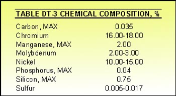
Generally, materials furnished to this standard shall be 316, 316L, or other material agreed to by the purchaser and manufacturer. Where 316L is specified, materials shall conform to the requirements for chemical composition as prescribed in Table DT-3.
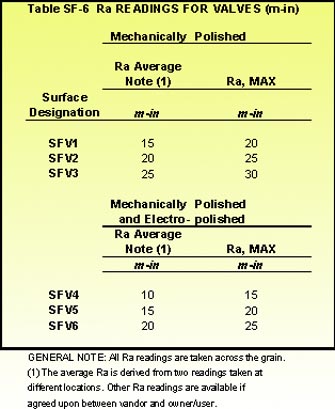
DT-12 SURFACE CONDITION The internal and external surfaces of fittings (valves) furnished to this standard may be finished using any combination of mechanical polishing, chemical polishing, and electro-polishing conforming with Part SF (Table SF-6). All surfaces shall be cleaned to remove oils, grease, particulates, and grinding compounds or electrolytes.
ASME/BPE-1997, GR-10 TERMS AND DEFINITIONS
Annealing: a treatment process for steel for the purpose of reducing hardness, improving machinability, facilitating cold working, or producing a desired mechanical physical, or other property.
Aseptic: free of pathogenic (causing or capable of causing disease) microorganisms.
Aseptic processing: operating in a manner that prevents contamination of the process.
Automatic welding: welding with equipment that performs the welding operation without adjustment of the controls by a welding operator. The equipment may or may not perform the loading and unloading of the work (see machine welding).
Bioprocessing: the creation of a product utilizing living organisms.
Bioprocessing equipment: equipment, systems, or facilities used in the creation of products utilizing living organisms.
Cavitation: a condition of liquid flow where, after vaporization of the liquid, the subsequent collapse of vapor bubbles can produce surface damage.
Certification: documented testimony by qualified authorities that a system qualification, calibration, validation, or revalidation has been performed appropriately and that the results are acceptable.
cGMPs: current Good Manufacturing Practices. Current design and operating practices developed by the pharmaceutical industry to meet FDA requirements as published in the Code of Federal Regulations, Chapter 1, Title 21, Parts 210 and 211.
Clean: free of dirt, residues, detergents, or any contaminants that may affect or adulterate the product or process.
Clean-in-place (CIP): internally cleaning a piece of equipment without relocation or disassembly. The equipment is cleaned but not necessarily sterilized. The cleaning is normally done by acid, caustic, or a combination of both, with Water-for-injection (WFI) rinse.
Clean steam: steam free from boiler additives that may be purified, filtered, or separated. Usually used for incidental heating in pharmaceutical applications.
Cloudiness: the appearance of a milky white hue across some portion of a surface resulting from the electropolish process.
Dead leg: an area of entrapment in a vessel or piping run that could lead to contamination of the product.
Demarcation: a localized area that is dissimilar to the surrounding areas with a defined boundary after electropolishing.
Fermentation: the biochemical synthesis of organic compounds by microorganisms or cultivated cells.
Fermentor (fermenter): a vessel for carrying out fermentation.
Full penetration: a weld joint is said to be fully penetrated when the depth of the weld extends from its face into the weld joint so that the joint is fully fused. For a tube-to-tube weld, no unfused portions of the weld joint shall be visible on the inside diameter of a fully penetrated weld.
GMP facility: a facility designed, constructed, and operated in accordance with cGMP guidelines established by the FDA.
Heat number: an alphanumeric identification of a stated tonnage of metal obtained from a continuous melting in a furnace.
Hold-up volume: the volume of liquid remaining in a vessel or piping system after it has been allowed to drain.
Hydrotest: a pressure test of piping, pressure vessels, or pressure-containing parts, usually performed by pressurizing the internal volume with water at a pressure determined by the applicable code.
Hygienic: of or pertaining to equipment and piping systems that by design, materials of construction, and operation provided for the maintenance of cleanliness so that products produced by these systems will not adversely affect human or animal health.
Hygienic clamp joint: a tube outside diameter union consisting of two neutered ferrules having flat faces with a concentric groove and mating gasket that is secured with a clamp, providing a nonprotruding, recessless product contact surface.
Liquid penetrant indication: refer to ASME BPVC, Section V, Article 6, para. T-600, for testing an anomaly or an indication.
Machine welding: welding with equipment that performs the welding operation under the constant observation and control of a welding operator. The equipment may or may not perform the loading and unloading of the works (see automatic welding).
Micron or micrometer (mm): one-millionth of a meter.
Orange peel: an appearance of a pebbly surface.
Passivation: a final treatment/cleaning process used to remove free iron or other anodic contaminants from the surfaces of corrosion-resistant steel parts such that uniform formation of a passive layer is obtained.
Passive layer: a passive oxidized film that forms naturally on the stainless steel surface when exposed to air or similar oxidizing environment protecting the underlying base metal from corrosion.
Pipe: Pipe size is determined by diameter and schedule. For bioprocessing equipment, pipe does not include tube.
Pitch: to cause to be set at a particular angle or slope. Degree of slope or elevation.
Porosity: cavity-type discontinuities formed by gas entrapment during solidification.
Pure steam: steam that is produced by a steam generator which, when condensed, meets requirements for Water-for-Injection (WFI).
Pyrogen: a fever-producing substance.
Ra: log of the arithmetic mean of the surface profile. Usually expressed in min as related to roughness(see ASME B46.1).
Self-draining: the elimination of all fluid from the system due to the force of gravity alone.
Square cut: a tube end cut perpendicular to the tangent plane.
Steam in place (SIP): the use of steam to sanitize or sterilize a piece of equipment without the use of an autoclave.
Sterile: free from living organisms.
Surface inclusion: particles of foreign material in a metallic matrix. The particles are usually compounds such as oxides, sulfides, or silicates, but may be a substance foreign to and essentially insoluble in the matrix.
Surface residual: a foreign substance that adheres to a surface by chemical reaction, adhesion, adsorption, or ionic bonding (for example, corrosion, rouging, and staining).
Tube: tube is sized by its nominal outside diameter. For bioprocessing equipment, tube does not include pipe.
Ball Valve Specifications for Clean and Pure Steam Applications
High Purity Ball Valves ½" thru 4"
High Purity ball valve shall be a three piece design with ISO 5211 Integral Actuator Mounting Pad, removable swing-out center section, non-exposed body bolting and encapsulated body seals. The ID of the valve flow path (ball, seats, ends) shall be the same ID as the tubing it is attached to as per ASME BPE 1997 SD.3.7.9.
Body Materials – 316L Stainless Steel ASTM A351 CF3M.
Ball Materials – 316L Stainless Steel ASTM A479 or ASTM A351 CF3M.
End Connections
Clamp style – 316L Stainless Steel A351 CF3M (dimensions per ASME BPE 1997 DT-10)
Extended Buttweld (ETO) - 316L ASTM A-270, Chemical composition and dimensions per ASME BPE 1997 table DT-3; and DT-5. Welding shall conform with ASME BPE 1997, MJ-7.2.3.
Stem – 316L Stainless Steel ASTM A479, Live-loaded, Blowout proof design. Packing seals to be a combination of PEEK (Poly Ether Ether Ketone) and NRG (filled TFE) and conforming to ASME BPE 1997 SG-4.1.1.1.
Seats – Pure TFM, (FDA, USP 23 Class VI), Non- slotted, designed to meet ASME BPE 1997 SD 3.6.1, SG-4.1.1.8, SG4.1.1.6 and rated for steam pressure of 150 psi at 366ºF.
Interior Finish – Polished to meet ASME BPE 1997 specification DT-12 and table SF-6.
Mechanical Polish to SFV 1
Electro-Polish to SFV 4
Markings – Valves shall be marked to conform with ASME BPE 1997 DT-3.
Packaging– Valves to be packaged to conform with ASME BPE 1997 DT-13.
Ball valve shall be SVF "CleanFLOW" Part # SB76666AT
Visit SVF Flow Controls at Interphex booth 177.
For more information: Wayne Ulanski, SVF Flow Controls, Inc., 13560 Larwin Circle, Santa Fe Springs, CA 90670. Tel: 562-802-2255; 800-783-7836. Fax: 562-802-3114.