
Water Level Sensing Using the Hydrostatic Technique

Mark A. Miller, Pressure Systems Inc.
Introduction
Theory
Barometric Pressure
Sensing Technology
Signal Conditioning
Dealing with the Environment
Packaging
Cable Vent Tube
Lightning and Other Transient Voltages
Introduction (Back to Top)
Water level monitoring is an important parameter in many municipal, environmental and process applications. In each case, the measurement technique and the hardware required must be carefully chosen to ensure that the data provided is sufficiently accurate and that the instrument operates reliably and with a minimum of maintenance. With few exceptions, the hydrostatic measurement technique has been proven to be one of the simplest, and therefore one of the most trouble-free and cost-effective methods available. The following information is provided to the specifying engineer as a basis for making informed decisions on behalf of his or her client. We include brief discussions on the theory and technology behind KPSI level measurement products, as well as recommendations for their proper use and care.
Theory (Back to Top)
Hydrostatic pressure may be used to indicate water level by the following relationship:
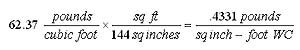
Given: Density of water at 60ºF = 62.37 pounds per cubic foot
So the pressure exerted by a water column one foot in height is
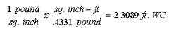
Another way to look at it is what height of water column is required to generate a pressure of one pound per square inch?
This example also illustrates the fact that the pressure exerted by a column of water depends only on the height of the column and is independent of the affected area. However, it is dependent on one other factor; i.e., the local barometric pressure acting on the surface of the liquid.
Barometric Pressure (Back to Top)
When designing a system for accurate determination of water level via the hydrostatic technique, the user must remember that the pressure sensed by the level transmitter is the total of the hydrostatic pressure generated by the liquid column plus the local barometric pressure acting on the surface of the liquid. See Figure A.
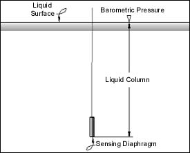
Figure A
Thus, in an uncompensated design such as an absolute or sealed gage configuration, a change in local barometric pressure will cause a change in transmitter output. For example, when calculated as a percentage of the full scale of 10 feet of water column, a change in barometric pressure of 0.1 inches of mercury will cause an error of greater than 1%. If this error is not acceptable, then a separate measurement of barometric pressure must be made and this value subtracted from the pressure indication given by the level transmitter. Because of the expense and complexity involved with the aforementioned scheme, standard KPSI level transmitters are configured to effect automatic compensation for barometric pressure changes. The simplest way to accomplish this is to vent the reference side of the sensor to local barometric pressure. Thus the same barometric pressure acts on opposite sides of the sensing diaphragm and the effect of changes are negated.
Sensing Technology (Back to Top)
The technology behind every KPSI submersible level transmitter or transducer is a media-isolated piezoresistive silicon pressure sensor. Silicon was first utilized to make pressure sensors in the late 1950s/early 1960s. Produced similarly to integrated circuits, silicon was chosen as a base material for, among other things, its near-perfect elasticity and low raw material and production costs. In production, boron atoms were first diffused (nowadays ion-implanted) into the crystal lattice of the silicon to create a classic four-arm Wheatstone bridge. Then the silicon is back-etched to create a diaphragm in the correct orientation to the strain resistors. Finally, when pressure is applied, the diaphragm flexes and the strain is sensed by the resistors, causing a bridge imbalance and an output proportional to the applied pressure.
For applications where the media is a clean, dry, non-corrosive gas, the sensor need only be mounted to a substrate and packaged so as to provide a means of electrical and pneumatic connection. Liquid and corrosive gas applications, however, require that the silicon sensor be isolated from the harmful media and in such a way so as not to detract from its inherent good qualities.
All KPSI sensors are isolated from the media by a metal diaphragm of 316 stainless steel (or other material, depending upon the application). The cavity behind the metal diaphragm is filled with a non-compressible fluid, usually silicone oil. Although simple in appearance, this package is a highly engineered isolation system. The diaphragm diameter, thickness and shape, the type of oil and how it is prepared for this application, the sensor attachment technique and many other parameters have been optimized through over thirty years of experimentation and field testing. Literally millions of sensors configured with this package are in use throughout the world, in applications ranging from oil exploration, where pressures and temperatures typically exceed 15000 pounds per square inch and 150ºC, respectively, to military and commercial aircraft where temperatures routinely cycle between 54º and +71ºC, several times a day! Reliability in these environments is a testament to the robustness of the design, especially when compared to the typical water level application. See Figure B.
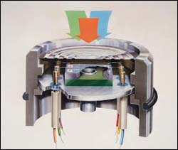
Figure B
Signal Conditioning (Back to Top)
The vast majority of level monitoring and control systems in existence are configured to accept an output from the level transmitter of 4-20 mA (2 wire). A much smaller number utilize level transducers with an output of 0-5 VDC (3 wire), and there are some particular data loggers that will only accept millivolt (4 wire) inputs. For now, suffice it to say that when a 4-20 mA or 0-5 VDC format is required, KPSI will combine the sensor with a signal conditioning circuit. This circuit typically (1) regulates the incoming voltage and generates stable voltage(s) upon which the circuit operates, (2) provides precision sensor excitation, (3) contains an instrumentation amplifier which conditions the millivolt output of the sensor to the desired format, and (4) includes null and gain adjustments for the purpose of setting the zero pressure and full scale outputs to the required setpoints. The process through which the sensor and conditioning circuit are calibrated requires a complete pressure and temperature test system, capable of generating precision test pressures to within 0.02% of Full Scale and holding test temperatures to within 0.1ºC. Otherwise there can be no guarantee that the products comply with published specifications.
Dealing with the Environment (Back to Top)
Once the sensor and signal conditioning circuit are calibrated, they must be packaged (enclosed) so as to accommodate the ambient environment where they are to be used. Long term submersion in clean or polluted water, raw sewage or any number of chemicals is the most obvious consideration. Less obvious and even more challenging, are harmful transient voltages, the worst of which are caused by lightning. See "Lightning and Other Transient Voltages" below. KPSI's standard circuit design has been upgraded and improved to make the unit more tolerant of surges. Additional protection should be supplied at the data acquisition end.
Packaging (Back to Top)
This step is especially critical in the case of submersible level transducers and transmitters, as the enclosure must insure that the signal conditioning circuit is adequately protected from the media while venting the sensor reference to local barometric pressure! The vast majority of KPSI level transducers and transmitters are housed in 316 stainless steel enclosures, with a smaller number utilizing other materials, depending on the application. One other transmitter maker claims that titanium alloy is superior to 316 stainless in every respect, but this simply is not the case. For example, 316 stainless is preferred over titanium when the media is highly acidic. In most other cases, titanium is overkill and drives up the cost of the product with no real benefit. On the other hand, for seawater applications, titanium is the preferred material and is optionally available from KPSI.
The KPSI enclosure design has been proven in over 10 years and thousands of units produced to be cost-effective and extremely reliable. The parts are produced in-house on modern computer-controlled turning centers. The assembly is completed on state-of-the-art orbital welding equipment, tested and re-tested for potential leak paths several times during the production process. The sensor is sealed to the enclosure with a fluorocarbon o-ring, a proven and trouble-free design that hasn't changed in more than 25 years. The cable is sealed to the enclosure via a compression gland, also of fluorocarbon. It is a simple and foolproof approach and much more flexible and cost-effective than vulcanized cable connections. On gage versions, barometric reference is accomplished via a small tube that forms the core of the cable. While critical to the barometric pressure issue, the user must consider other possible ramifications of the presence of this vent tube.
Cable Vent Tube (Back to Top)
Since it is hollow, the vent tube constitutes a pathway via which foreign material can enter the transducer enclosure, the most troublesome of which is moisture. While not difficult to solve, this issue must be taken seriously by the user or long-term reliability will be sacrificed.
As received, the cable vent tube contains air with a certain level of water vapor (humidity) that was present during the manufacturing process. If the cable is ever subjected to a temperature at or below the dewpoint of the air in the vent tube, the water vapor entrained in the air will condense into liquid. It is possible, therefore, that this condensation could occur when the transmitter and cable are lowered into ground water and certainly during shipment, especially if the shipment method is via air or if transport to the job site is in the back of a pickup truck during the winter! Furthermore, if condensation begins or continues to occur after the transmitter is installed, the pressure in the lower end of the tube will drop, causing more air (and potential water vapor) to be drawn into the vent tube, adding more condensation, . . . a vicious circle of sorts.
KPSI's solution to this potential problem includes (1) elimination of any water vapor present in the vent tube as received from the cable manufacturer, plus (2) prevention of additional vapor incursion after installation in the field. Prior to attachment of the cable onto the transmitter enclosure, the entire cable is purged with dry nitrogen. This purging pushes any water vapor that may be present out of the vent tube and replaces it with a dry, inert gas.
Once the cable has been installed onto the transmitter enclosure, a desiccant-filled Vent Filter is connected to the vent tube. Provided at no extra charge with all new transmitters, this Filter is intended to remain in place continuously, except during installation of the level transmitter, at which time it may be disconnected but only for as long as it takes to complete the cable routing process. The desiccant contained in the vent filter is highly hygroscopic, meaning that it will absorb any water vapor contained in the air during the normal venting process. As the desiccant becomes saturated, however, the Vent Filter must be replaced, in order to maintain dry conditions within the vent tube. If the installation does not lend itself to periodic inspection and replacement of the vent filter, an option available exclusively to users of KPSI level transmitters is our aneroid bellows.
Patterned after the bellows found within many mechanical barometers, the KPSI Aneroid Bellows is fitted to the vent tube in place of the desiccant-filled Vent Filter. Custom molded from extremely flexible rubber, the Bellows responds to changes in atmospheric pressure and telegraphs the change down the vent tube to the sensor. Because it is a closed system, the need for periodic maintenance is completely eliminated. These bellows are optionally available with new transmitters or may be retrofitted to existing installations. See Figure C.
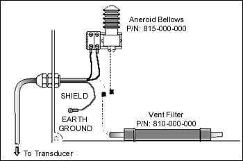
Figure C
Note: When installing bellows in the field, take care that water hasn't entered the cable. If you're unsure, send it back to the factory where new cable and the bellows will be installed.
Lightning and Other Transient Voltages (Back to Top)
Whether deployed to monitor water level in a deep well, reservoir, stream bed or wet/clear well, submersible transmitters are in direct contact with a conductive substance…water! Therefore any transient (temporary) voltage that occurs in the ground is easily conducted to the transmitter enclosure. There are many reasons why a transient voltage can occur in the ground, of which the most well known, and the least understood, is lightning. Transient voltages caused by a lightning strike will travel through the ground along the path of least resistance, sometimes from as far away as two miles, putting objects suspended in groundwater at risk. Nothing can protect equipment from a direct lightning strike, but there are two levels of protection that can reduce or eliminate damage due to remote lightning strikes.
The vented cable supplied with KPSI submersible transmitters contains a shielding layer of braided or wrapped copper that completely surrounds the conductors. Likewise, the enclosure surrounds the transmitter electronics. The cable shield is connected to the transmitter enclosure and is terminated in a blue wire at the loose end of the cable. By connecting this blue wire to a good earth ground, such as a copper grounding rod, low level transient voltages can usually be diverted to ground and away from the transmitter electronics before causing damage.
The next level of protection is accomplished through the use of line protectors. In order to be completely effective, the protectors must (1) be installed in the correct locations and (2) be highly responsive, high-current capable. High level transients can induce high voltage onto the transmitter cable conductors, sometimes even blowing a hole through the non-conductive cable jacket! This voltage will then travel both directions along the conductors, with the potential to damage the transmitter at one end as well as the power supply and readout at the opposite end. It is common practice to install a signal line protector only at the power supply end of the transmitter cable.
Unfortunately, this practice will only protect the power supply and readout from ground-based transients and does nothing to protect the submersible level transmitter. See Figure D.
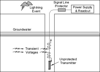
Figure D
By placing an additional signal line protector between the transmitter electronics and the cable, protection for the transmitter is accomplished. See Figure E.
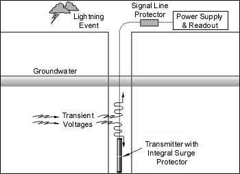
Figure E
KPSI manufactures a proprietary line of protectors specifically for this application. These devices are a hybrid design capable of reacting to the leading edge of the transient within nanoseconds and diverting current levels as high as 20,000 amperes until the transient has passed. Installation of the protector between the transmitter and the cable is accomplished at the factory by adding an extension to the transmitter housing. The other protector is provided in a DIN-3 rail mount configuration for installation at the cable termination.
As of this writing, KPSI is the only manufacturer of submersible level transmitters that offers this type of transient surge protection. It has been found to be so effective that it carries a warranty that runs for the life of the transmitter to which it is installed. If the engineer is specifying level monitoring instrumentation into a location which is known to suffer from lightning-related problems, this option should be recommended in the strongest possible terms. This option may also be factory retrofitted to existing transmitters and transducers during the course of a repair. Order KPSI Option-009 (4-20 mA) or Option-012 (0-5 VDC).
For more information: Mark Miller, Sr. Applications Specialist, Pressure Systems, Inc., 34 Research Dr., Hampton, VA 23666. Tel: 757-865-1243. Fax: 757-766-2644.