
Podbielniak Contactor: A Unique Liquid-Liquid Extractor - Part 1
Gitesh Dubal, B&P Process Equipment and Systems LLC
Introduction
Process Fundamentals
Mechanical Features
Principles of Operation
Process Feasibility
Process Variables
Introduction (Back to Top)
The Podbielniak Contactor, popularly known as the "Pod," is a liquid-liquid centrifugal extractor and separator (Figure 1) providing differential countercurrent extraction in a compact hermetic rotor. Used successfully for more than fifty years to solve extraction problems in the chemical process industry, the Pod can provide up to 5 theoretical stages in one unit and can separate liquids with a specific gravity difference as low as 0.01. The Pod has a bright future in new technologies as indicated by ongoing research in non-conventional applications.
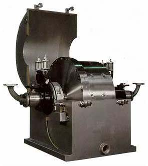
Figure 1: The Podbielniak Contactor, aka ‘the Pod'
This paper covers mechanical and operational features of the Pod. Part 2 examines its limitations, advantages, and applications.
Process Fundamentals (Back to Top)
The Pod operates on two principles: separation and extraction. Separation effectiveness is a function of the density difference, separation force, and the residence time at that separation force. In a centrifuge like the Pod, the centrifugal force creates a separation force many times normal gravity, denoted by Xg. As the Xg force is increased, lower residence time is required for a given separation. The process in which a component is removed from one solvent by contact with another immiscible solvent is called extraction. An optimal solvent has a high distribution coefficient, meaning the solute favors the solvent phase many times more than the feed phase.
Mixer-settlers are the most basic equipment for extraction. Typically, mixer-settlers have low efficiency, long settling time, require a lot of space, and are labor-intensive. Another extraction device, the sieve plate column, is also known as perforated tray tower. As seen in Figure 2, it is a cylindrical column with perforated bands that act like multiple countercurrent mixer-settlers. Liquids are forced countercurrently through the perforations, leading to intense contact between the two liquids and generation of interfacial surface area for mass transfer.
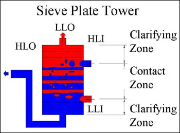
Figure 2: Sieve plate column
The Podbielniak extractor is analogous to a sieve plate column that is rotated about the top. In other words, the height of the sieve plate column is equivalent to the radius of the Pod. Multiple Xg force allows generation of a large interfacial area in a fraction of the sieve plate tower's volume. The Podbielniak contactor has perforated cylindrical bands that serve the same purpose as the horizontal plates in the sieve plate tower.
Mechanical Features (Back to Top)
The Podbielniak contactor is a horizontally mounted centrifuge. The Pod has perforated, concentric cylindrical bands that fit into grooves on the rotor at one end and the endplate at the other. As seen in Figure 3, the rigid inner shaft supports the rotor, and also provides the ports that serve as process liquid inlets and outlets. The shaft is drilled almost to the center from each side, but not through. There is a central channel and an annular channel on both the sides. This provides the four channels needed for process liquid flow.
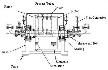
Figure 3: Mechanical features of a Pod
Feed tubes are provided inside the rotor for each inlet and outlet that connect to the shaft. These tubes extend to the rim and are drilled into the rotor for added stability. These tubes are cross-drilled at the appropriate radius to provide an inlet or outlet for a liquid. The unique mechanical design of the Pod offers the following features:
- Stability. Horizontal orientation provides increased stability compared to vertical centrifuges. This robust configuration makes the centrifuge more tolerant to vibrations caused by process upsets. The rotor is supported by widely spaced bearings, which also increases stability. The bearings are oversized due to flow requirements, providing a L10 bearing life of greater than 100,000 hours. Low operating RPM compared to other centrifuges leads to longer life of rotating parts.
- Hermetic. The Pod is flooded with the process liquids during operation. The Pod is equipped with mechanical seals in order to facilitate hermetic operation. As the Pod is flooded with process liquids at all times, internal volume usage is maximized.
- Ease of Operation. Podbielniak contactors are automated by the use of a variable frequency drive. The only mechanical monitoring required is for speed, lubrication flow for the bearings and product flow for wetting of the mechanical seals. Once the Pod is up and running, it requires minimal supervision.
- Versatility. The elements are customized for each application, taking into consideration variables like flow rates, percentage and properties of solids in feed, viscosity of material, etc. The Pod elements can be tailored for systems with solids in order to minimize the solids buildup, reducing downtime due to cleanup. Some feed tubes can be removed from the rim, which provides access to the inside of the rotor for cleanup without disassembly. To accommodate for corrosive materials, the Pod has been manufactured out of alloys such as Hastelloy C, Monel, Inconel, Alloy 20, etc.
Principles of Operation (Back to Top)
As seen in Figure 4, the heavy liquid (HLI) is introduced near the shaft, and the light liquid (LLI) is introduced near the rim of the rotor. As a result of the centrifugal force and density difference, the heavy liquid is forced out to the rim. As the heavy liquid propagates through the perforations, it displaces an equal volume of light liquid towards the shaft. The two liquids flowing countercurrently are forced to pass each other through the perforations on each band, leading to intense contact. The light liquid is collected at the shaft (LLO), and the heavy liquid is collected at the rim (HLO). This countercurrent series of dispersion and coalescence allows multi-stage extraction.
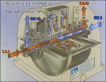
Figure 4: Flow through a Pod
The internal volume of the Pod is divided into three cylindrical zones based on the radial position of the two liquid inlets. The countercurrent contact zone is the volume enclosed between the two inlet radii. In this zone, the two liquids are forced countercurrently through the perforations leading to intimate contact and maximum surface area generation for mass transfer.
Inboard of the contact zone is light liquid clarification zone, where the light liquid is settled and entrained heavy liquid is removed. Similarly, the heavy liquid clarification zone, which is outboard of the contacting zone, clarifies the heavy liquid before it exits the Pod.
Process Feasibility (Back to Top)
The criteria for process feasibility in a Pod are that the two liquids are at least partially immiscible and have a density difference. If the two liquids are totally miscible, they cannot be physically separated. In addition, the flow streams should not have more than 30 to 40% (v/v) solids. The Pod extractor is manufactured in the various sizes, with capacities ranging from 0.4 GPM for the A-1 model test unit to as high as 600 GPM for the E-48. The capacities are derated for systems with solids, low density difference and viscous liquids.
Process Variables (Back to Top)
The major variables involved with the Pod operation are pressures, flowrates and Xg force. The inlet pressures are constant and are a function of the rotor speed and density difference. The outlet pressures are variable and are used to control the quality of the effluent streams. The LLO pressure reflects the position of the major interface inside the Pod, which allows dispersion of a selected liquid into the other in order to maximize interfacial surface area for mass transfer.
The flow rate ratio and cumulative flow rate can be varied to optimize a Pod extraction process. As the amount of solvent used (in other words, the flow rate ratio) is increased, the degree of extraction increases as well. Theoretically, the maximum dispersion of the two liquids is performed when all the trays in the contact zone are operating near flooding levels. As a rule of thumb, the Pod is operated at a cumulative flow rate around 85% of flooding rate, so that there is some room for fluctuation in feed conditions.
The Xg force, which is a function of RPM, dictates the maximum flow rate that the Pod can handle. The Xg force can be increased to provide additional separation force. The Xg force can be reduced at lower flow rates to operate the Pod at close to flooding conditions in order to get better extraction. Other variables that can affect an extraction process are feed conditions like concentration and temperature.
End of Part 1
For more information: Gitesh Dubal, Process Engineer, B&P Process Equipment and Systems LLC, 1000 Hess Ave., Saginaw, MI 48601. Tel: 517-757-1300. Fax: 517-757-1301.